25
FAULT INDICATION CIRCUITRY
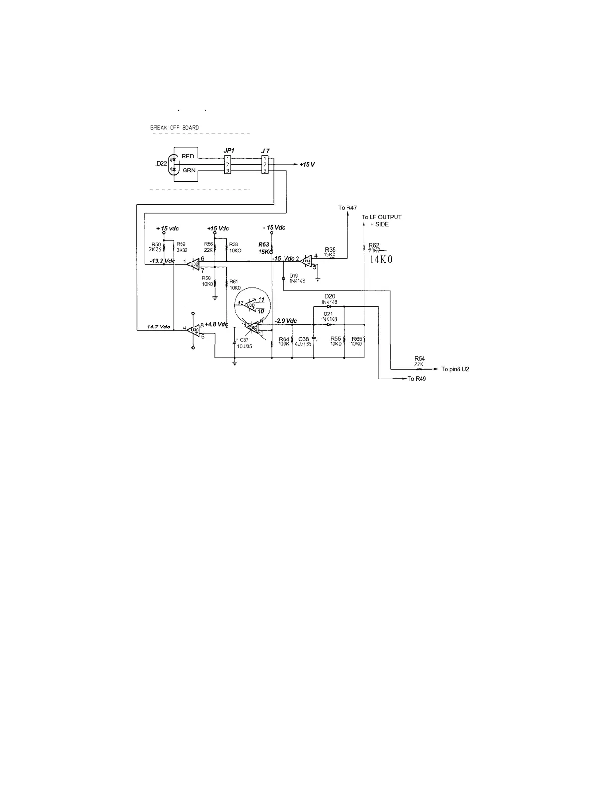
The detection circuitry for the LSR28P revolves around the quad comparator NJM2901N
(U3). There are a number of individual faults monitored for including voltage offset on both the
low and high frequency amplifiers, excessive current usage by the unit, and an over-limit input
signal level resulting in clipping. Providing that the circuitry is functioning correctly, the basic
power operational status is active when the green LED illuminates. When this occurs,
verification of proper audio operation is still necessary. If, however, the red LED or a
combination of the red and green LED’s illuminate, the circuitry has detected a fault or there is a
fault in the detection circuitry itself. In either case, the muting circuitry will be instantaneously
activated to turn off the drive to the power outputs and, hence, avoid the possibility of damaging
the transducers
From the above circuit, U3D in combination with U3C detects voltage offset from the
low and high frequency amplifiers through D21/R62 and D20/R54, respectfully, illuminating the
red led. They also detect excessive output or clipping through the network of R62/R65/R64 and
C38. Clipping indicates that the signal-input level is too high. U3A detects thermal shutdown
and power supply problems through R35 and R47.