39
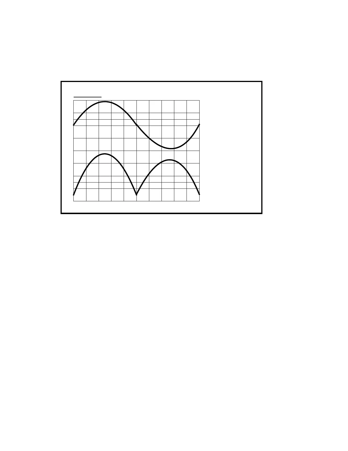
Excessive Second harmonic distortion in output
Output Waveform
Distortion Waveform
Figure B
(Second Harmonic)
Refer to Figure B above and note the character of second harmonic distortion. This is caused by
an imbalance in amplifying capability in either the current amplifier or the voltage amplifier.
Note that the “Distortion Waveform” could also be inverted in relation to above depending on
the polarity of the imbalance. Place a probe on the output of the amp and adjust for around 40V
P/P if the condition of the board allows this much voltage. Visually note the characteristics of
the waveform and then probe on both sides of C1. C1 is across the input to the current amp. If
the waveform visibly appears almost identical to the output waveform (same P/P voltage, same
waveform shape) then the problem lies in the voltage amp. Proceed to “Voltage Amp Test”. If
there is much difference between the output waveform and the waveforms measured at C1 there
is probably a problem in the current amp.
• No output from the amplifier when driven.
Verify signal base of Q18. If there is no signal refer to ‘Low Frequency Filter Test”.
Verify that 1UB pin 7 is close to +15 volts. If not refer to “Amplifier Muting Test.” If
all of the above is correct, refer to “Voltage Amplifier Test.”
• Does Amplifier oscillate? Does Amplifier roll off too soon at high frequencies?