44
Low Frequency Filter Test
Turn on generator output A, adjust frequency for 900Hz, and adjust oscillator level to obtain 3V
P/P at the input to the filter, pin 1 of J3. Move probe to junction of R48 and C23.
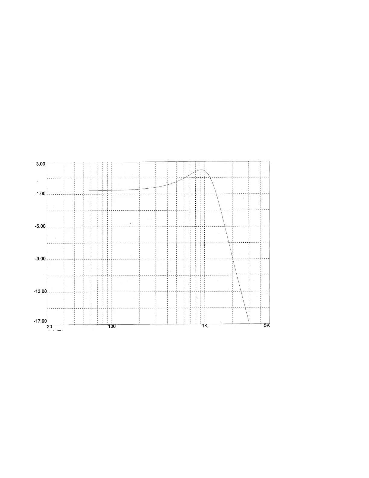
The curve on the graph shown above represents the transfer function in dB of the first filter
section at U1A when this section is operating properly.
Sweep the oscillator frequency and note if the readings are reasonably,
close to the values indicated in the plot above (+/-10%) For example, with a filter
that operates normally, the output will be 2.8 P/P at 20Hz, 3.2V P/P at 500Hz, 3.75v
P/P at 900 Hz, 1.1 V P/P at 2 kHz, 150mV P/P at 5 kHz and 33 mV P/P at 10 kHz.
Low Pass Filter Response
Frequency (Hz)
This is a low-pass filter with the half power point at 1500 Hz. If the response is incorrect check
the values of RZ1, R33, CY1, CX1 and C22. If these values are okay, check the values of C23,
C24, R48 and R42.