EasyManua.ls Logo

JBL SCS 138-178 User Manual

JBL SCS 138-178
16 pages
To Next Page IconTo Next Page
Page #1 background imageLoading...
Page #1 background image
SIMPLY CINEMA - SCS 138-178 Subwoofer
Service manual V1 (E)
SPECIFICATIONS:
Active Subwoofer Section
• Low Frequency Cut-off: 35Hz
• High Frequency Cut-off: 40Hz - 120Hz Variable
• Built-In Amplifier Power: 100 Watts RMS
• Drive Units: 200mm Paper Cone Long Throw Driver
Bass Reflex Enclosure
• Dimensions (H x W x D): 450mm x 250mm x 360 mm
• Weight: 13.6kg
Question and Answer IconNeed help?

Do you have a question about the JBL SCS 138-178 and is the answer not in the manual?

JBL SCS 138-178 Specifications

General IconGeneral
BrandJBL
ModelSCS 138-178
CategorySubwoofer
LanguageEnglish

Summary

Simply Cinema Subwoofer Specifications

Active Subwoofer Performance Details

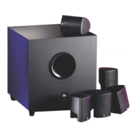
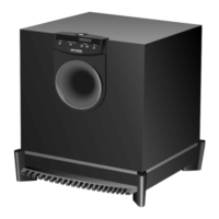
Details on low and high frequency cut-off points, amplifier power, and drive units for the active subwoofer.

Physical Enclosure and Dimensions

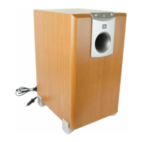
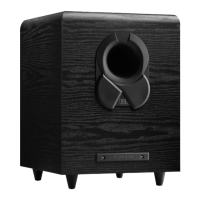
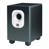
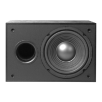
Information on the bass reflex enclosure, physical dimensions, and weight of the subwoofer.

Component Parts List

PCBs, ICs, and Resistors

Listings for PCB assemblies, integrated circuits, and various resistors.

Resistors and Capacitors

Details on resistors and various types of capacitors including disc, electrolytic, and mylar.

Capacitors, Transistors, and Diodes

Listings for capacitors, transistors, and diodes with their specifications.

Transistors, Diodes, Connectors, Fuses, Switches

Details on transistors, diodes, connectors, fuses, and switches.

ICs, Transistors, and Connectors

Listings for integrated circuits, transistors, and connectors.

Miscellaneous Components

Details on LEDs, diodes, capacitors, transformers, cords, fuses, and switches.

Circuit Schematics Overview

Main Subwoofer Schematic

The main circuit diagram showing signal paths and component interconnections.

Limiter Circuit Schematic

Schematic detailing the limiter circuit section of the subwoofer.

Detailed Circuit Schematics

Power Supply and Amplifier Stages

Schematics covering the power supply and amplifier circuitry.

Protection and Input/Output Circuits

Diagrams for protection mechanisms and input/output signal handling.

New Limiter Circuit Schematic

Limiter Amplifier and Control

Schematic details of the new limiter circuit, including operational amplifiers and transistors.

PCB Layout Diagrams

Main Board PCB Layout

Top-side view of the main printed circuit board layout.

Sub-Board PCB Layout

Printed circuit board layout for a sub-board component.

Component Placement Diagrams

Visual representation of component placement on printed circuit boards.

Specific Component Layouts

Layouts showing placement for specific components like ICs, resistors, and switches.

Related product manuals