Do you have a question about the JBL ARC SUB10 and is the answer not in the manual?
General warning about hazardous voltages and risk of electric shock during service.
Unit has no power switch; hazardous voltages are present when plugged in.
Procedures for testing leakage current and resistance before returning unit to customer.
Importance of replacing components marked with IEC symbol with exact replacements.
Specifies the RMS output power of the subwoofer amplifier.
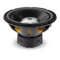
Details the type and material of the 10-inch driver used in the subwoofer.
Lists the types of audio inputs supported by the subwoofer.
Specifies the available output connections from the subwoofer.
Indicates the setting for the high-pass filter when using speaker-level inputs.
Defines the range of audible frequencies the subwoofer can reproduce.
Provides the physical height, width, and depth of the subwoofer.
States the weight of the subwoofer unit.
Specifies the operating voltage ranges for US and EU models.
Details amplifier type, THD, damping factor, and output power characteristics.
Defines the signal levels required for optimal input response.
Lists SNR measurements for various weighting types.
Specifies the impedance of the line and speaker level inputs.
Details specifications for the speaker low-pass and subsonic filters.
Adjusts the subwoofer's volume relative to the system.
Indicates unit status: RED for standby, GREEN for signal present.
Sets the highest frequency the subwoofer reproduces for seamless transition.
Connects to receiver/processor pre-amp or subwoofer out jacks.
Connects to main speaker outputs for receivers without pre-amp out.
Ensure rated voltage matches AC source to prevent damage.
External checks, control settings, and driver inspection before disassembly.
Step-by-step guide to safely remove the amplifier assembly from the cabinet.
Checks for blown fuses, capacitor bulges, shorts, and component continuity.
Guide for connecting the subwoofer using line-level RCA inputs.
Guide for connecting the subwoofer using speaker-level inputs.
Steps to diagnose no sound when using speaker-level inputs.
Tips for addressing issues with reduced bass output.
Steps to diagnose no sound when using line-level inputs.
Procedure for basic functional testing using signal generators.
Testing the unit's response using a sweep generator for noise detection.
Procedure for testing the driver's resistance and mechanical integrity.
Addresses performance issues caused by cold solder connections on the power amp module.
Specific complaints like 'Dead, No Output, or Motorboating' requiring solder joint checks.
Details failure of capacitor C6 and its recommended replacement part.
Complaint of 'no output' linked to capacitor C6 damage.
Guide on replacing front panel components, addressing the sealed cover.
Explains the sealed cover protecting air-tight integrity as a factor.
Detailed steps for accessing and servicing front panel components.
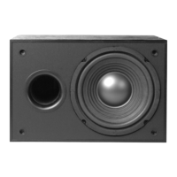
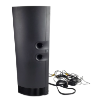
Diagram showing the assembly of the ARC SUB10 cabinet and its parts.
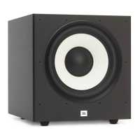
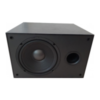
Diagram showing the assembly of the DS-10 cabinet and its parts.
Exploded view illustrating the packaging materials for the DS-10 model.
Exploded view illustrating the packaging materials for the ARC SUB10 model.
Diagram of the component layout on the PLAIN 5 PCB.
Diagram of the solder side trace layout on the PLAIN 5 PCB.
Diagram of the component layout on the PLAIN 5.1 PCB.
Diagram of the solder side trace layout on the PLAIN 5.1 PCB.
Procedures and safety notes for installing the S53AMI/S64AMI Power Amp module.
Pin configuration details for the LM324 Quad Op Amp integrated circuit.
Pin diagrams for various transistors used in the amplifier module.
| amplifier power | 100 watts |
|---|
| driver size | 10 inches |
|---|
| inputs | Line- and high-level |
|---|---|
| outputs | High-level with high-pass filter at 180Hz |
| crossover frequency | 50Hz – 150Hz |
|---|---|
| frequency response | 35Hz – 150Hz |
| dimensions | 11-1/2 x 17-1/8 x 16-1/2 inches |
|---|---|
| dimensions metric | 292 x 435 x 419mm |
| weight | 27 lbs/12.3 kg |