03 - Attachments, Couplings and Load Handling
09 - Lift Arm Quickhitch
06 - Hydraulic Quickhitch
03 - 9 9813/2850-3 03 - 9
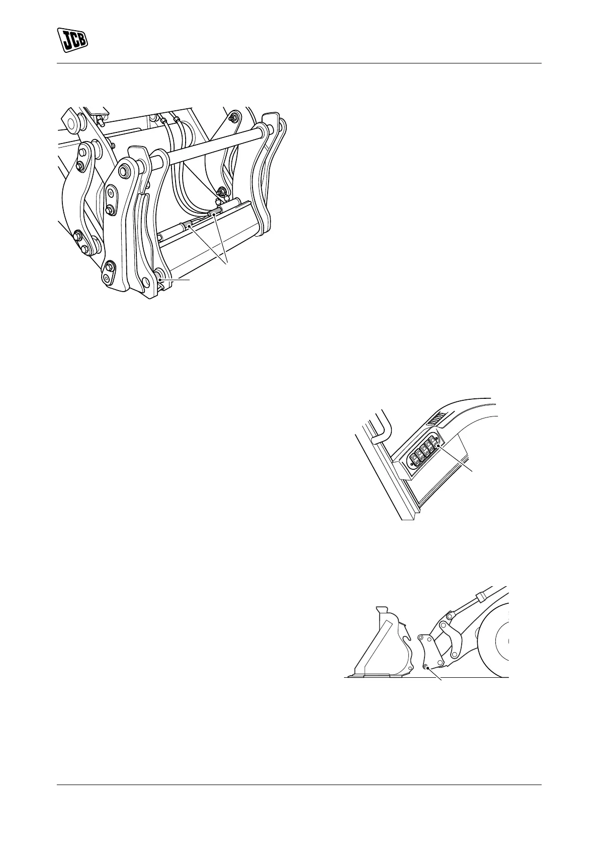
Figure 9.
A Locking pins
B Indicators
Lubricate
Remove the attachments before you grease the
locking pins. Total of 2 grease points. Refer to Figure
9.
When working in difficult conditions, grease and
operate the locking-pins every 10 hours.
Disconnect and Connect
Disengage the Attachment
In this procedure to disengage the attachment,
the Quickhitch isolator switch is used to divert the
hydraulic power.
1. Park the machine on solid, level ground.
2. Lower the lift arm until the attachment is on the
ground.
2.1. Servo-controls levers: Push the applicable
lever forward to lower the attachment.
2.2. Multi-controls levers: Push the applicable
lever forward to lower the attachment.
3. Engage the park brake and put the transmission
in neutral.
3.1. If necessary, disconnect the hydraulic
hoses.
4. Push and hold the Quickhitch isolator switch.
Figure 10.
A Quickhitch isolation switch
5. Disengage the red locking pins: Refer to Figure
11.
Figure 11.
B Red locking pins