About the Product
Operator Station
17 9821/7050-4 17
Operator Station
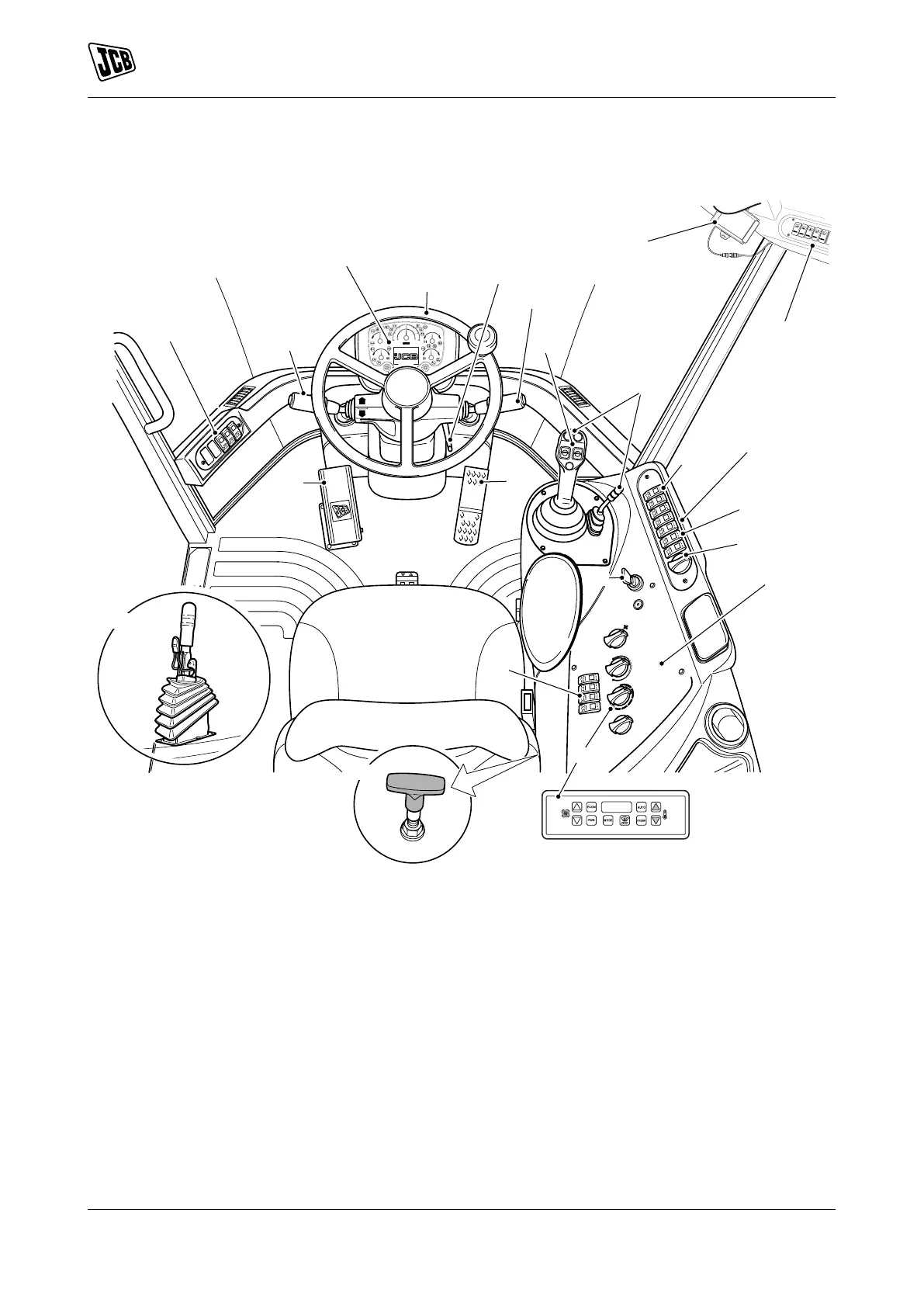
Component Locations
Figure 8.
A Steering wheelRefer to: Operation > Drive Controls > Steering Wheel (Page 68).
B TransmissionRefer to: Operation > Drive Controls > Forward, Neutral and Reverse Switch
(Page 69).
C Power outletRefer to: Operation > Power Sockets > Auxiliary Power Socket (Page 102).
D Accelerator pedalRefer to: Operation > Drive Controls > Accelerator Pedal (Page 68).
E Service brake pedalRefer to: Operation > Drive Controls > Service Brake Pedal (Page 69).
F Drive controls, switches and instruments (Depending on machine specification)Refer to: Operation >
Drive Controls (Page 63).
G Instrument clusterRefer to: Operation > Instruments (Page 73).
H Right console switchesRefer to: About the Product > Console Switches (Page 19).
J Multi purpose steering column switchRefer to: Operation > Drive Controls > Steering Column
(Page 68).
K Operating leversRefer to: Operation > Operating Levers/Pedals (Page 85).
L Starter switchRefer to: About the Product > Interior Switches > Ignition Switch (Page 23).
M Heater / Air conditioning operationRefer to: Operation > Heating, Ventilating and Air-Conditioning
(HVAC) (Page 98).
N Left console switchesRefer to: About the Product > Console Switches (Page 19).
O Loader arm control isolation switchRefer to: About the Product > Console Switches > Controls
Isolation (Page 21).