15 - Engine
12 - Crankshaft
00 - General
15 - 81 9813/6900-6 15 - 81
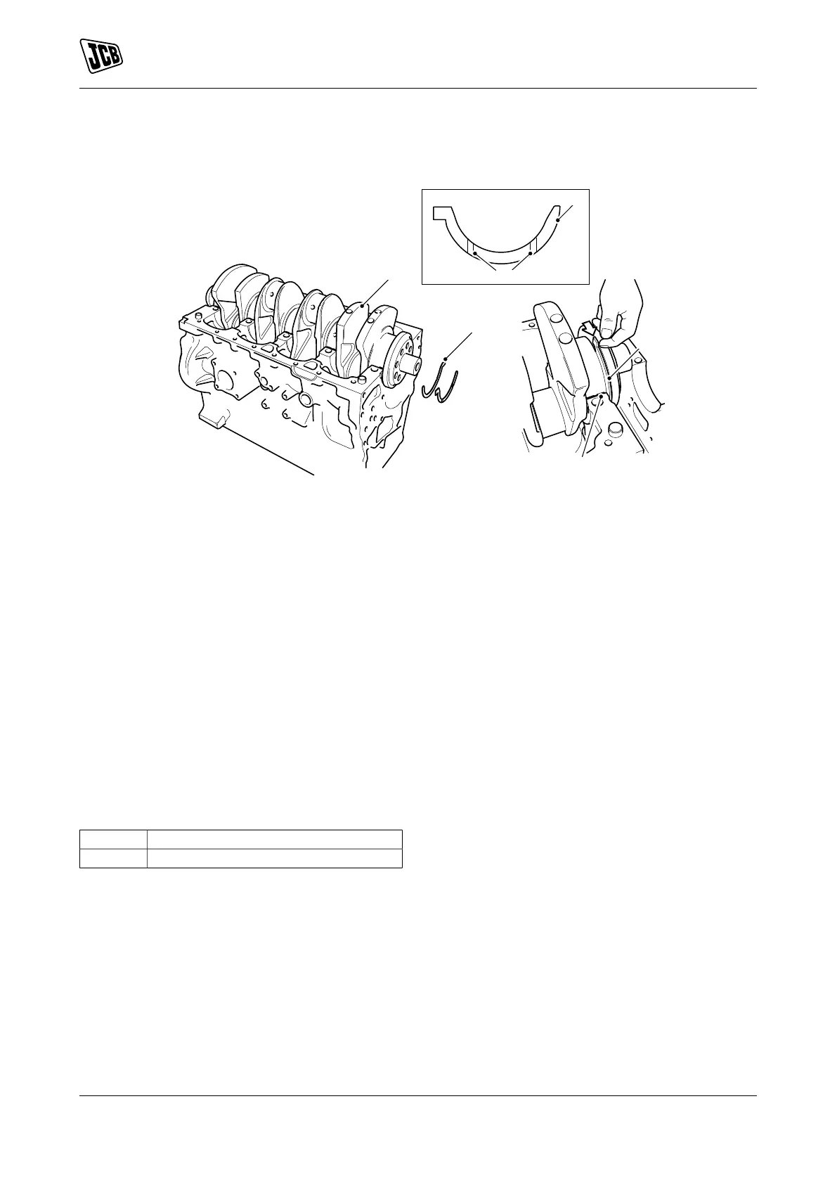
Figure 295.
A Thrust washers B Crankshaft
C Rear main bearing H Oil slot - thrust washers
6.1. Slide the thrust washers between the
crankshaft and the crankcase rear main
bearing.
6.2. Make sure that they are installed in the
correct positions, with the two slots facing
outwards from the bearing saddle.
6.3. If necessary, push the crankshaft forward
and then backwards to obtain clearance to
install the thrust washers.
6.4. DO NOT rotate the crankshaft, the bearing
shells can become dislodged, refer to step
4.
7. Check that the crankshaft end float is within
service limits, refer to Technical Data (PIL 15-12).
Table 101. Torque Values
Item Nm
F 24
 Loading...