Section 1 - General Information
Standard Torque Settings
Hydraulic Connections
1-12 1-12
9803/9360-3
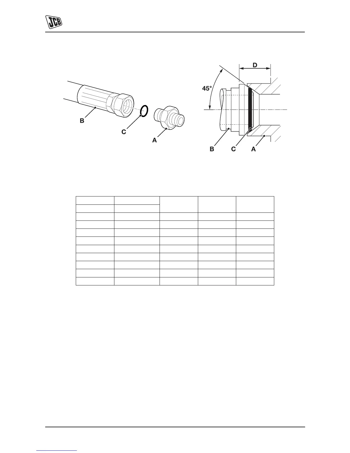
Hoses Screwed into Adaptors
Fig 2.
Hoses 2-B screwed into adaptors 2-A seal onto an `O' ring
2-C which is compressed into a 45° seat machined into the
face of the adaptor port.
Note: Dimension 2-D will vary depending upon the torque
applied.
Table 10. BSP Hose - Torque Settings
BSP Hose Size Hexagon (A/F)
Nm kgf m lbf ftin. mm
1/8 14.0 14.0 - 16.00 1.4 - 1.6 10.3 - 11.8
1/4 19.0 24.0 - 27.0 2.4 - 2.7 17.7 - 19.9
3/8 22.0 33.0 - 40.0 3.4 - 4.1 24.3 - 29.5
1/2 27.0 44.0 - 50.0 4.5 - 5.1 32.4 - 36.9
5/8 30.0 58.0 - 65.0 5.9 - 6.6 42.8 - 47.9
3/4 32.0 84.0 - 92.0 8.6 - 9.4 61.9 - 67.8
1 38.0 115.0 - 126.0 11.7 - 12.8 84.8 - 92.9
1 1/4 50.0 189.0 - 200.0 19.3 - 20.4 139.4 - 147.5
1 1/2 55.0 244.0 - 260.0 24.9 - 26.5 180.0 - 191.8