18 - 4
Operation
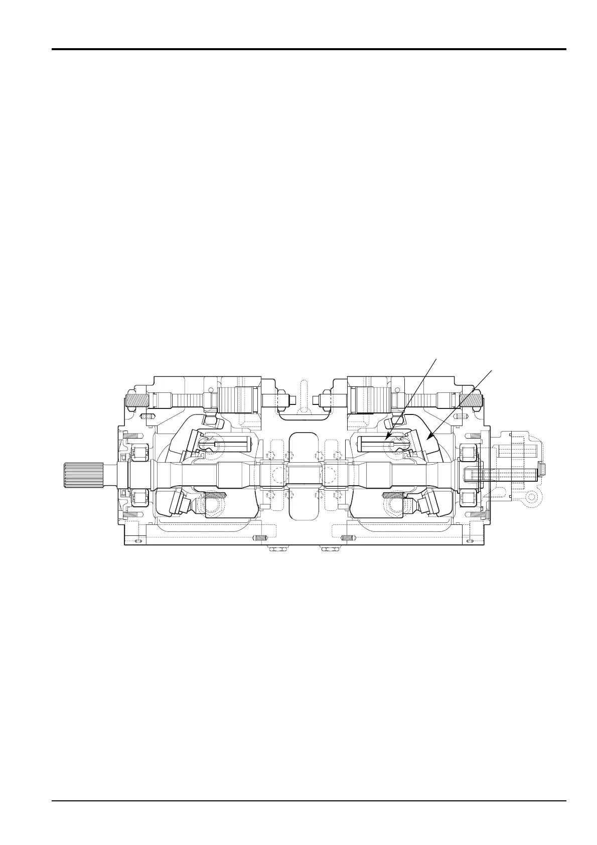
Main Pumps (P1 and P2)
Each pump P1 or P2 consists of a cylinder block, containing
nine piston/shoe assemblies. Driven by shaft, the block
rotates between a variable angle, non-rotating swash plate
and a fixed valve plate.
A retainer plate and a set of cylinder springs hold the piston
shoes against the swash plate. Due to the angle of the
swash plate, as the cylinder block rotates the pistons are
forced to move back and forth in their cylinders. The piston
stroke, and therefore the pump displacement, varies
according to the swash plate angle, which is controlled by
machine demand.
The fixed valve plate contains two crescent shaped ports.
The valve plate is located so that when a piston reaches its
nearest point to the plate it comes into line with the pump
inlet port. During the next 180° of cylinder block rotation the
piston draws oil into the cylinder bore. When the piston
reaches its furthest point from the plate it ceases to be in
line with the inlet port and comes into line with pump outlet
port. The next 180° of cylinder block rotation causes the
piston to force oil from the cylinder bore through the outlet
port.
The process is carried out sequentially by all the pistons to
provide a continuous smooth pump output.
Section E Hydraulics
9803/6410
Section E
18 - 4
Issue 1
Hydraulic Pump/Regulator JS130, JS160
SWASH PLATE
PISTON ASSEMBLY
PUMP 2
PUMP 1