18 - 13
Hydraulic Pump (cont’d)
Assembly (cont’d)
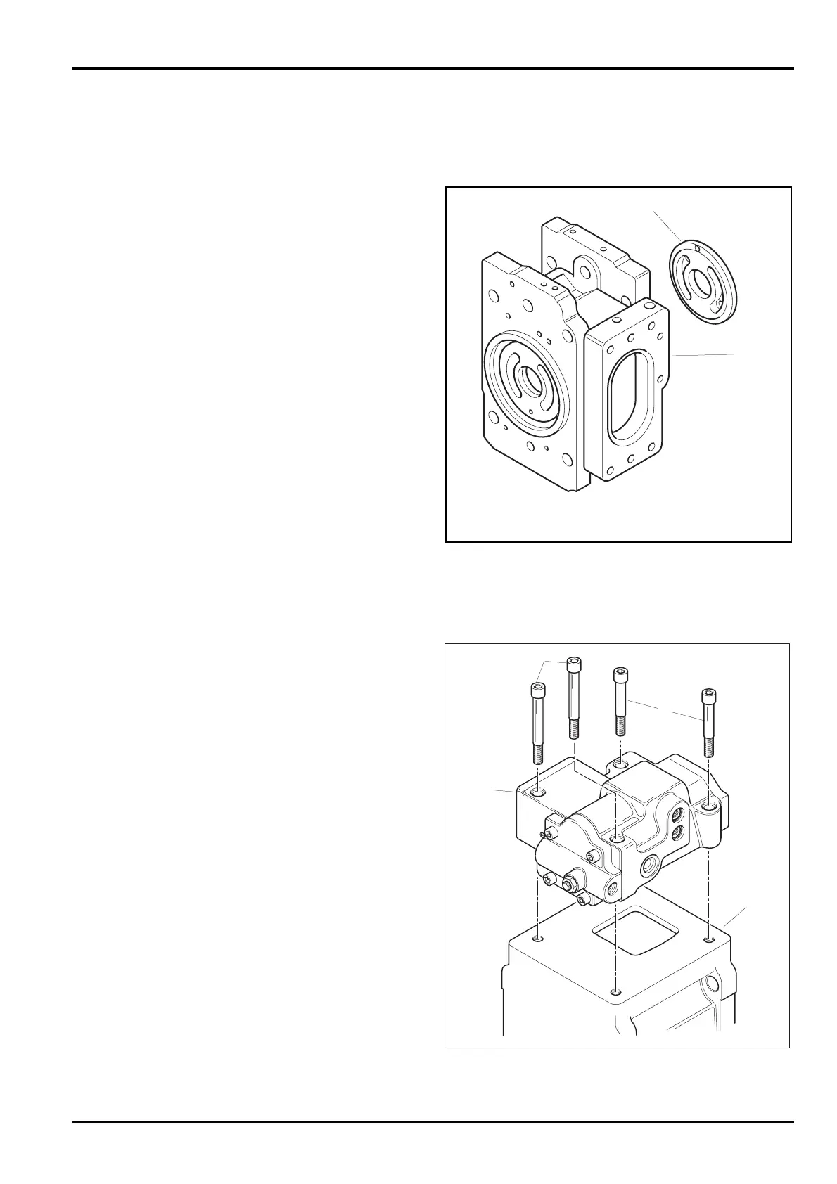
7 Attach valve plate 25 to valve block 8, engaging the
location pin in the process. Check that the suction and
delivery ports of the plate are not transposed.
8 Insert splined coupling 31 into valve block 8. Ensuring
that new ‘O’ rings are positioned on joint faces, fit the
valve block to pump casing 5, taking care to align the
match marks. Engage the spline on shaft 21 with the
splined coupling. Secure with the four socket head
screws 7, tightened to a torque of 235 Nm (173 lbf ft).
9 Refit regulator 4 to pump casing 5 using a new ‘O’ ring.
Take care to locate the feedback pin of tilting lever 29
with the lever of the regulator. Secure the regulator with
socket head screws 2 and 3, tightened to a torque of 30
Nm (22 lbf ft).
10 Refit gear pump assembly 6. Tighten the securing
screws 6A to a torque of 7 Nm (5 lbf ft).
Section E Hydraulics
9803/6410
Section E
18 - 13
Issue 1
Hydraulic Pump/Regulator JS130, JS160