13 - 4
Assembly (cont’d)
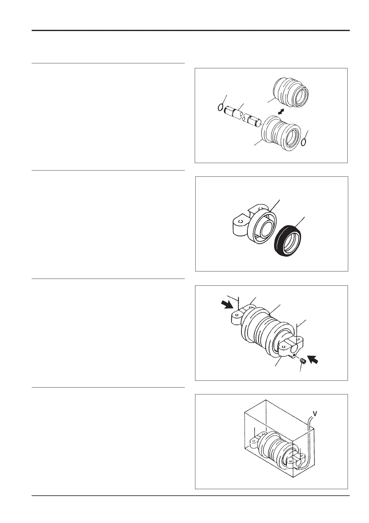
3 Coat shaft C with grease. Insert the shaft into roller H or
J. Apply grease to new 'O'-rings G and install them on
shaft C.
4 Install new floating seals F into brackets D and E. Coat
the metallic face of each seal with engine oil.
5 Press mounting brackets D and E onto shaft C and
partially insert new locking wires B.
Wrap sealing tape around one plug A with one thread
remaining uncovered. Install this plug, but leave the
other one out until after pressure testing (step 6).
6 Connect compressed air pipe V to the vacant plug A
port. Using extreme care to prevent water entering the
assembly, lower it into a tank of water.
Apply air pressure of 1.9 bar (28 lbf/in
2
) and check that
there are no bubbles leaking from the unit. If leakage
occurs dismantle and re-assemble, taking extra care
when fitting new seals.
Section J Track and Running Gear
9803/6410
Section J
13 - 4
Issue 1
Bottom Roller
J
G
C
G
H
F
B
E
B
A
D
C
D,E
JS01600