27 - Driveline
06 - Semi-Automatic Gearbox
12 - Clutch - Ratio
27 - 128 9813/6850-2 27 - 128
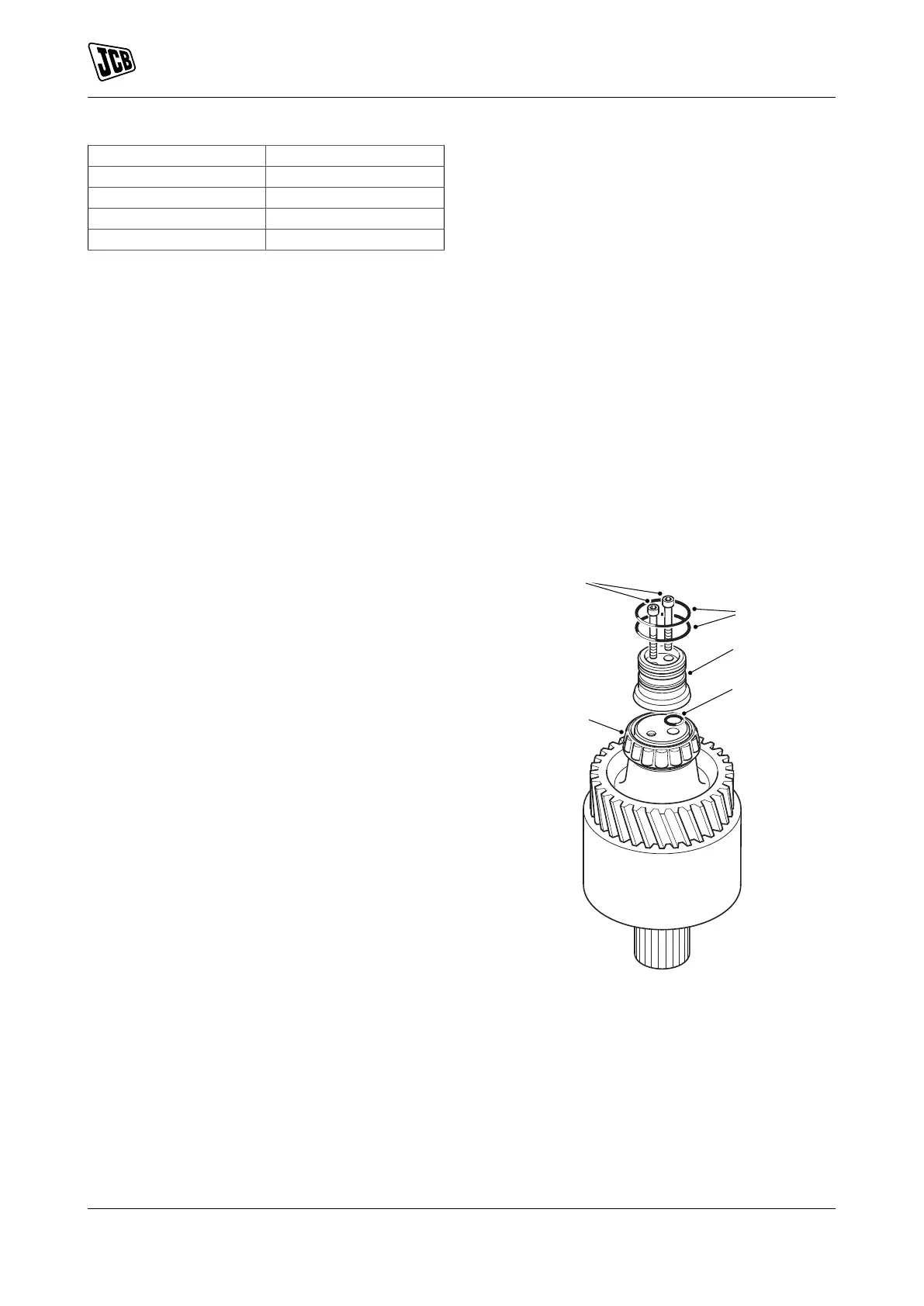
Item Description
P O-ring seal 3
Q Housing
R Gallery port
S O-ring seal 1
Assembly
Assembly is the opposite of the disassembly
procedure with the following precautions.
1. Install the new clutch piston O-ring seals 2 and
seal 3 to the piston.
2. Lubricate the new seals and push the piston into
the housing by hand.
3. Put the lower spring cup over the central spigot
of the piston.
4. Replace the spring and the top spring cup.
5. Keep the circlip 2 on the top cup ready for
installation.
6. Use the tube with a cutout to compress the
spring.
7. Locate the cutout to give access for circlip 2.
8. Install the circlip 2 and make sure that it is seated
correctly in the groove.
9. New clutch friction plates must be soaked in oil
before assembly.
10. Install the first counter plate to the clutch drum
followed by the friction plate.
11. Alternately install all fourteen plates.
12. Use a scrap splined drive hub to align the splines
of the friction plates.
13. Install the thick counter plate at the top of the
assembly followed by the circlip 1.
14. Check the free play clearance of the clutch plates
and it must be within the specified limit.
Dimension: 3 –3.5 mm
15. You can adjust the clearance by either changing
the thick pressure plate from 6.0mm (0.24in)
thick version to 6.5mm (0.26in) thick or by
the addition of a shim counter plate installed
immediately under the thick pressure plate.
16. Once the clutch is assembled completely then
apply compressed air to the gallery port in the
end of the shaft to check the clutch operation.
Ratio Clutches
Disassembly
1. For the remaining two ratio clutches follow the
same disassembly procedure as above.
2. The only difference is the retention of the support
taper roller bearing which for each clutch is held
in place by a machined cap.
Assembly
1. Clutch 1 and clutch 2 assembly.
1.1. Use a mandrel to carefully push the taper
bearing 1 into its position.
1.2. Rotate the roller cage as the bearing is
pushed into place to make sure that the
mandrel does not foul and distort the cage.
1.3. Put the new O-ring seal 4 into the grooves
in the cap 1.
Figure 569.
T Taper bearing 1
U O-ring sea l4
V Cap 1
W Capscrews 1
X O-ring seals 5
1.4. Two capscrews 1 hold the cap 1 in place.
1.5. Tighten the capscrews 1 to the correct
torque value.
1.6. Put two new O-ring seals 5 into the groves
in cap 1.
 Loading...
