INSTALLATION
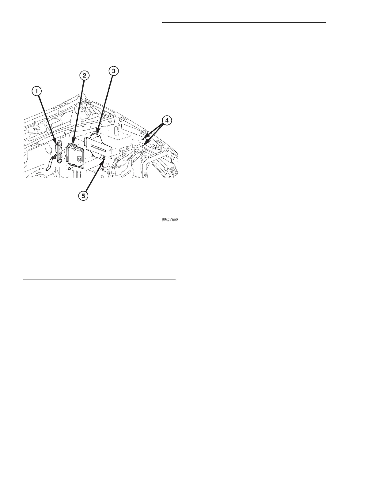
(1) Install ECM on bracket (Fig. 2).
(2) Position ECM and bracket assembly in vehicle
(Fig. 2).
(3) Install ECM bracket to inner fender retaining
nuts (Fig. 2).
(4) Connect ECM electrical connectors (Fig. 2).
(5) Connect negative battery cable.
TRANSMISSION CONTROL
MODULE
DESCRIPTION
The electronic control system consists of various
components providing inputs to the TCM. The TCM
monitors transmission sensors, shifter assembly
switches, and bus messages to determine transmis-
sion shift strategy. After shift strategies are deter-
mined, the TCM controls the actuation of
transmission solenoids, which controls the routing of
hydraulic fluid within the transmission, by moving a
sequence of four valves to make a shift occur.
The W5J400 electronic transmission has a fully
adaptive control system. The system performs its
functions based on continuous real-time sensor feed-
back information. In addition the TCM receives infor-
mation from the PCM/ECM (engine management)
and ABS (chassis systems) controllers over the CAN
C bus. The CAN C bus is a high-speed communica-
tion bus that allows real time control capability
between various controllers. Most messages are sent
every 20 milliseconds. This means critical informa-
tion can be shared between the transmission, engine,
and ABS controllers. The CAN C bus is a two wire
bus with a CAN C Bus (+) circuit and a CAN C Bus
(-) circuit. These circuits are twisted pairs in the har-
ness to reduce the potential of radio and noise inter-
ference.
The transmission control system automatically
adapts to changes in engine performance, vehicle
speed, and transmission temperature variations to
provide consistent shift quality. The control system
ensures that clutch operation during up-shifting and
downshifting is more responsive without increased
harshness. The TCM activates the solenoid valves
and moves valves in the valve body to achieve the
necessary gear changes. The required pressure level
is calculated from the load condition, engine speed.
Vehicle speed (from ABS module) and transmission
oil temperature, matched to the torque to be trans-
mitted. Power for the transmission system is sup-
plied through the shifter mechanism (no
transmission control relay). The TCM (Fig. 3) is
located in the center console, on the right side of the
transmission tunnel.
OPERATION
The transmission control module (TCM) deter-
mines the current operating conditions of the vehicle
and controls the shifting process for shift comfort and
driving situations. It receives this operating data
from sensors and broadcast messages from other
modules.
The TCM uses inputs from several sensors that are
directly hardwired to the controller and it uses sev-
eral indirect inputs that are used to control shifts.
This information is used to actuate the proper sole-
noids in the valve body to achieve the desired gear.
The TCM continuously checks for electrical, mechan-
ical, and some hydraulic problems. When the TCM
detects a problem, it stores a Diagnostic Trouble
Code (DTC).
The shift lever sensor assembly (SLSA) has sensors
that are monitored by the TCM to calculate shift
lever position. The reverse light switch, an integral
part of the SLSA, controls the reverse light relay con-
Fig. 2 ENGINE CONTROL MODULE (ECM)
REMOVAL/INSTALL
1 - ECM ELECTRICAL CONNECTORS
2 - ENGINE CONTROL MODULE (ECM)
3 - ECM MOUNTING BRACKET
4 - ECM MOUNTING BRACKET MOUNTING STUDS
5 - MOUNTING BRACKET RETAINING NUTS
8Ea - 4 ELECTRONIC CONTROL MODULES WG
ENGINE CONTROL MODULE (Continued)














 To Next Page