© Jeff Rowland design gRoup 2007. all Rights ReseRved.
23
STEP 7: Test the remote with the CAPRI
Stereo Preamplifier to make sure that the
units operate properly together.
STEP 8
:
After verifying proper operation,
replace the remote housing and reinstall the
two screws that secure the housing.
STEP 3: Locate jumper position J1 on the
rear panel board of the unit. Using needle-
nose pliers, move the jumper from between
pins 1 and 2 to pins 2 and 3. (See FIGURES
4 and 5)
STEP 4: Replace the bottom cover.
Using
a 5/64" hex wrench, reinstall the nine
screws that secure the bottom cover to the
CAPRI chassis.
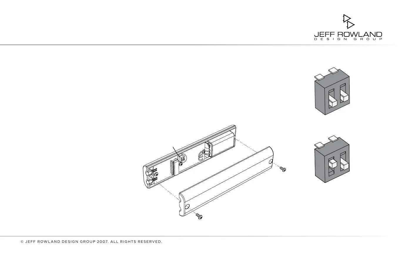
STEP 5: Using a #1 Phillips head screw-
driver, remove the two screws that secure
the remote transmitter housing. Open
the housing.
STEP 6:
Locate switch position
SW7
.
Adjust slider #1 on the switch. This switch
now corresponds with the new setting on
jumper J1 of the rear panel board.
SWITCH SW7
FIGURE 6: Remote transmitter housing
with details of switch position SW7
FIGURE 7: Detail of switch
position sw7
SWITCH SW7 POSITION 1
(DEFAULT)
SWITCH SW7 POSITION 2
1
O
N
2
1
O
N
2