WIRING
CONNECTIONS
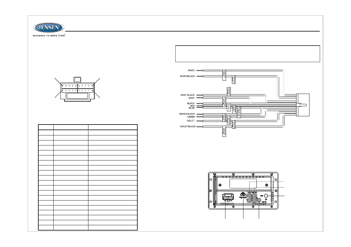
The wiring diagram depicts all the wiring connections required for proper
operation of the unit.
The wiring diagram depicts all the wiring connections required for proper
operation of the unit.
110
1120
DETAIL A
PIN NO. WIRE COLOR
DESCRIPTION
1 VIOLET/BLACK
REAR RIGHT SPEAKER (-)
VIOLET
REAR RIGHT SPEAKER (+)
GREEN
REAR LEFT SPEAKER (+)
GREEN/BLACK REAR LEFT SPEAKER (-)
N/A N/A
GRAY FRONT RIGHT SPEAKER (+)
GRAY/BLACK FRONT RIGHT SPEAKER (-)
N/A N/A
WHITE/BLACK FRONT LEFT SPEAKER (-)
WHITE FRONT LEFT SPEAKER (+)
N/A N/A
N/A N/A
N/A N/A
BLUE AMP REMOTE (+12VDC 100mA)
RED +12VDC SWITCHED
BLACK GROUND
N/A N/A
N/A N/A
N/A N/A
N/A N/A
2
3
4
5
6
7
8
9
10
11
12
13
14
15
16
17
18
19
20
SHOWN FROM PIN VIEW
WARNING: Wiring harness comes with stripped and tinned leads to aid in the
installation process. Any unused speaker wires must have their exposed ends cut
off or insulated individually.
10AMPFUSE
6
JWM45
WIRING HARNESS
CONNECTOR
HDMI
OUTPUT
(ARC)
VIDEO OUTPUT
AM/FM ANTENNA
SOCKET
AUDIO INPUT
AUDIO OUTPUT