1 888 275 4538 MVP GROUP .7 | P a g e
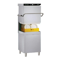
Fig. 5
2- Connect the solenoid valve, which feed the machine, to water shut valve, using a flexible hose. Each
machine must have its own water supply.
2A1 – WATER SUPPLY PRESSURE
Check that dynamic water supply pressure, measured between the appliance and the main, is between 200
and 500kPa. If the pressure is too high, install a pressure regulator on the inlet pipe. If the pressure is low,
install an additional external pressure motor pump. (par.1D – Technical Data)
- In case of new or long term appliance inactivity, drain the water line to eliminate air bubbles and foreign
bodies present in new or unused water lines, which can damage the machine.
2A2 – WATER HARDNESS
If water hardness is higher than acceptable, install a water softener if in the machine is not provided with an
internal one, of adequate size prior the feed solenoid valve.
(par.1D – Technical Data)
If there is a high concentration of mineral residues in the water or high conductivity, we recommend
installing the demineralization filter for 5/7° f.
2A3 – MODELS WITH FREE FALL (GRAVITY) DRAINAGE
N.B.
The drainage line consists of a sump pit (floor drain), free flow, of proper size capable to evacuate twice
the water flow indicated on the data diagram. It must be near to the drain pipe of the machine without
bending, stretching the pipe.
- The drain line must reach the sump pit with free flow without restraints, stretching, bends, kinks, or being
forced.
- Connect the waste outlet pipe to the main drain pipe.
2A4 – MODELS WITH DRAIN PUMP
- This unit does not have a drain pump for waste water.