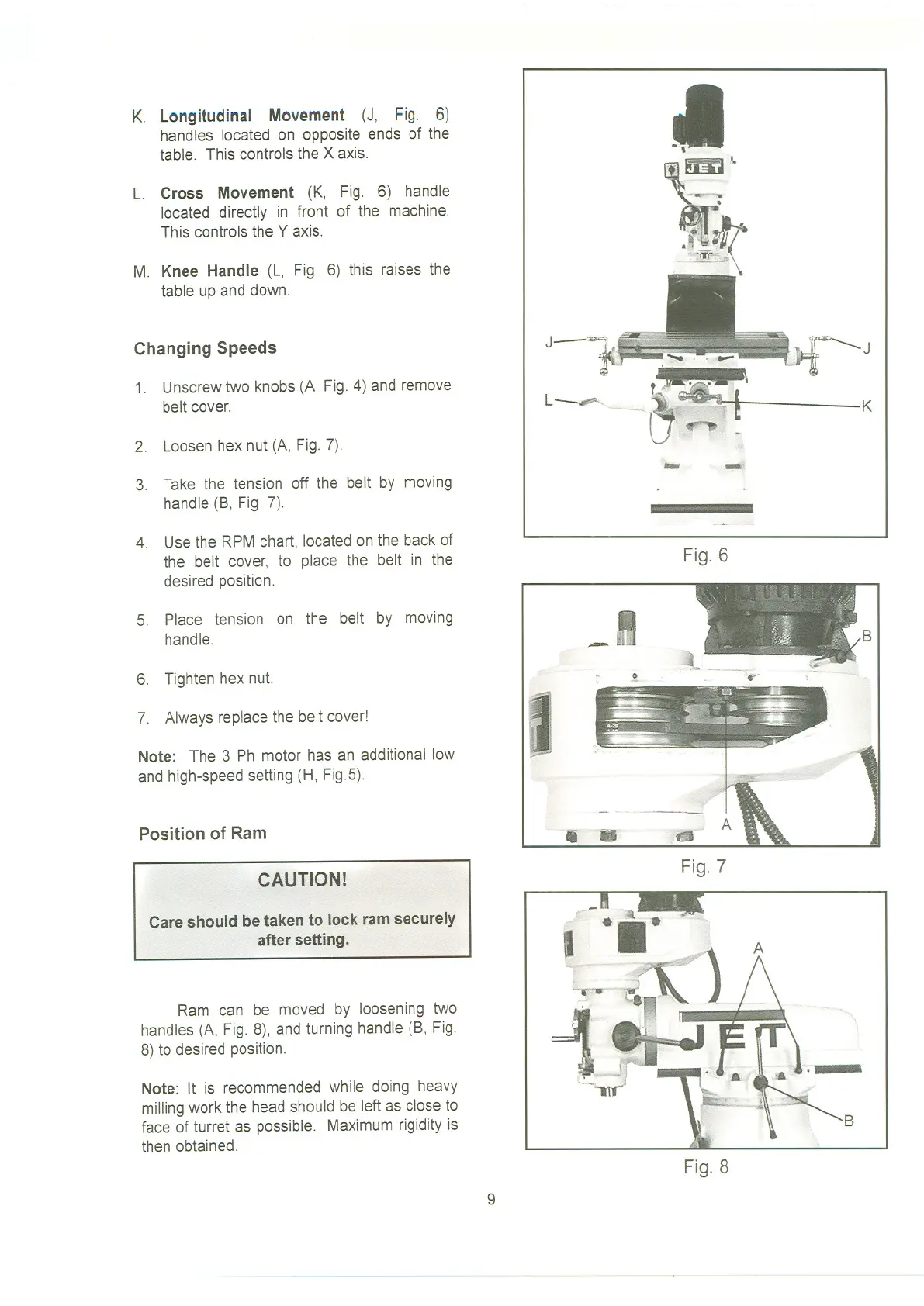
K. Longitudinal Movement (J, Fig. 6)
handles located on opposite ends of the
table. This controls the X axis.
L. Cross Movement (K, Fig. 6) handle
located directly in front of the machine.
This controls the Y axis.
M. Knee Handle (L, Fig. 6) this raises the
table up and down.
Changing Speeds
1. Unscrew two knobs (A, Fig. 4) and remove
belt cover.
2. Loosen hex nut (A, Fig. 7).
3. Take the tension off the belt by moving
handle (B, Fig. 7).
4. Use the RPM chart, located on the back of
the belt cover, to place the belt in the
desired position.
5. Place tension on the belt by moving
handle.
6. Tighten hex nut.
7. Always replace the belt cover!
Note: The 3 Ph motor has an additional low
andhigh-speedsetting(H, Fig.5).
Position of Ram
CAUTION!
Care should be taken to lock ram securely
after setting.
Ram can be moved by loosening two
handles (A, Fig. 8), and turning handle (B, Fig.
8) to desired position.
Note: It is recommended while doing heavy
milling work the head should be left as close to
face of turret as possible. Maximum rigidity is
then obtained.
I
K
..... -,'
Fig.6
I
'
~:'
_II
.
Fig.7
B
Fig.8
9
 Loading...