Controls
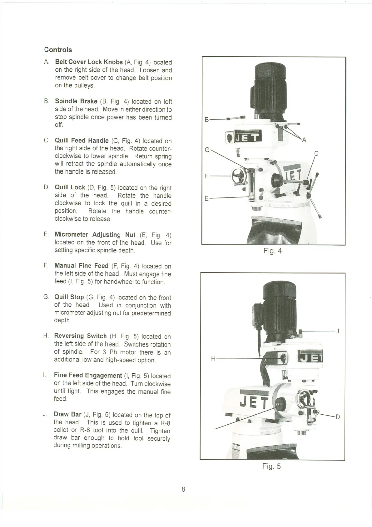
A. Belt Cover Lock Knobs (A, Fig. 4) located
on the right side of the head. Loosen and
remove belt cover to change belt position
on the pulleys.
B. Spindle Brake (B, Fig. 4) located on left
side of the head. Move ineither directionto
stop spindle once power has been turned
off.
C. Quill Feed Handle (C, Fig. 4) located on
the right side of the head. Rotate counter-
clockwise to lower spindle. Return spring
will retract the spindle automatically once
the handle is released.
D. Quill Lock (0, Fig. 5) located on the right
side of the head. Rotate the handle
clockwise to lock the quill in a desired
position. Rotate the handle counter-
clockwise to release.
E. Micrometer Adjusting Nut (E, Fig. 4)
located on the front of the head. Use for
setting specific spindle depth.
F. Manual Fine Feed (F, Fig. 4) located on
the left side of the head. Must engage fine
feed (I, Fig. 5) for handwheelto function.
G. Quill Stop (G, Fig. 4) located on the front
of the head. Used in conjunction with
micrometer adjusting nut for predetermined
depth.
H. Reversing Switch (H, Fig. 5) located on
the left side of the head. Switches rotation
of spindle. For 3 Ph motor there is an
additional low and high-speed option.
I.
Fine Feed Engagement (I, Fig. 5) located
on the left side of the head. Turn clockwise
until tight. This engages the manual fine
feed.
J. Draw Bar (J, Fig. 5) located on the top of
the head. This is used to tighten a R-8
collet or R-8 tool into the quill. Tighten
draw bar enough to hold tool securely
during milling operations.
G
B-II"""-"-
F
E
Fig. 4
J
H
".. CI
Fig. 5
8
 Loading...