Do you have a question about the Jet JVM-836 and is the answer not in the manual?
Details general warranty duration and conditions for JET products and accessories.
Specifies who is covered and what defects are covered, along with limitations.
Explains warranty limitations, how state law applies, and exclusions.
Provides instructions for technical support and where to find more product information.
Lists various product categories with their corresponding warranty durations.
Essential safety guidelines for operating the turret mill, covering general practices and personal protection.
Alerts users to potential hazards from dust containing chemicals like lead, silica, arsenic, and chromium.
Rules for safe machine operation, including handling adjustments, grounding, and workpiece clamping.
Emphasizes maintaining a clean work area, controlling access, and undivided attention for safety.
Explains the meaning of CAUTION and WARNING symbols used in the manual for safety alerts.
Details motor type, horsepower, voltage, phase, and sound emission levels.
Lists spindle taper, quill diameter, speed ranges, and head movement capabilities.
Provides dimensions, travel limits, T-slot sizes, and weight capacity for the machine table.
Gives overall assembled and shipping dimensions, plus net and shipping weights.
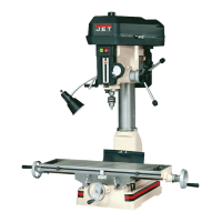
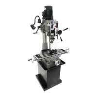
Illustrates the installation layout and key dimensions of the JVM-836 milling machine.
Instructions for unpacking the machine, checking for damage, and verifying contents against the list.
Guidelines for preparing the installation site and procedures for safely lifting the milling machine.
Steps for raising the mill head to its upright position and initial tightening of securing nuts.
Critical safety warning about making electrical connections by qualified personnel and proper grounding.
Instructions for converting the JVM-836-1 model from 115V to 230V operation.
Table specifying recommended wire sizes for branch circuits based on conductor length.
Identifies and describes the function of various operating controls on the milling machine.
Important safety precautions to observe before and during mill operation, including spindle brake and rigidity.
Steps for securely clamping a workpiece to the milling machine table using T-slots, clamps, and blocks.
Procedure for changing spindle speed by adjusting the belt on the pulleys, referencing speed charts.
How to engage and disengage the manual fine feed for precise spindle movement using the handwheel.
Instructions for using the draw bar to install and remove tooling from the spindle collet.
Procedure for tilting the mill head left or right and ensuring it's perpendicular to the worktable.
Instructions for sliding the ram fore/aft and rotating it on the turret for optimal setup.
Guidance on adjusting gibs for the knee, saddle, and table to reduce vibration and improve accuracy.
Procedure for adjusting the ram wear plate using a dial indicator for precise fit and reduced play.
Instructions on adjusting lead screw backlash for smooth table movement and accuracy.
Chart showing spindle speed settings for single-phase motor configurations based on pulley positions.
Chart detailing spindle speed settings for 3-phase motor configurations based on pulley positions.
Information on how to order replacement parts and what information to provide to the service department.
Exploded view diagram of the JVM-836 head assembly, showing component relationships.
Comprehensive list of parts for the JVM-836 head assembly with index numbers and descriptions.
Exploded view diagram of the JVM-836 upper head assembly, detailing its components.
Parts list for the JVM-836 upper head assembly, including part numbers and quantities.
Exploded view diagram of the JVM-836 leadscrew assembly, illustrating its parts.
Parts list for the JVM-836 leadscrew assembly, with part numbers and descriptions.
Exploded view diagram of the JVM-836 base assembly, showing its constituent parts.
Parts list for the JVM-836 base assembly, including part numbers and quantities.
Exploded view diagram of the one-shot lubrication system, showing its components.
Parts list for the one-shot lubrication system components.
Wiring diagram for the 1-phase JVM-836-1 model, showing low and high voltage configurations.
Wiring diagram for the 3-phase JVM-836-3 model, illustrating connections for 4/8 poles.
| Model | JVM-836 |
|---|---|
| Category | Drill |
| Type | Hammer Drill |
| Chuck Size | 13 mm |
| Drilling Capacity in Steel | 13 mm |
| Drilling Capacity in Wood | 40 mm |
| Max Drilling Capacity (Steel) | 13 mm |
| Max Drilling Capacity (Wood) | 40 mm |