computer radio control system
EN
2.2.
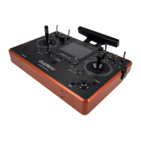
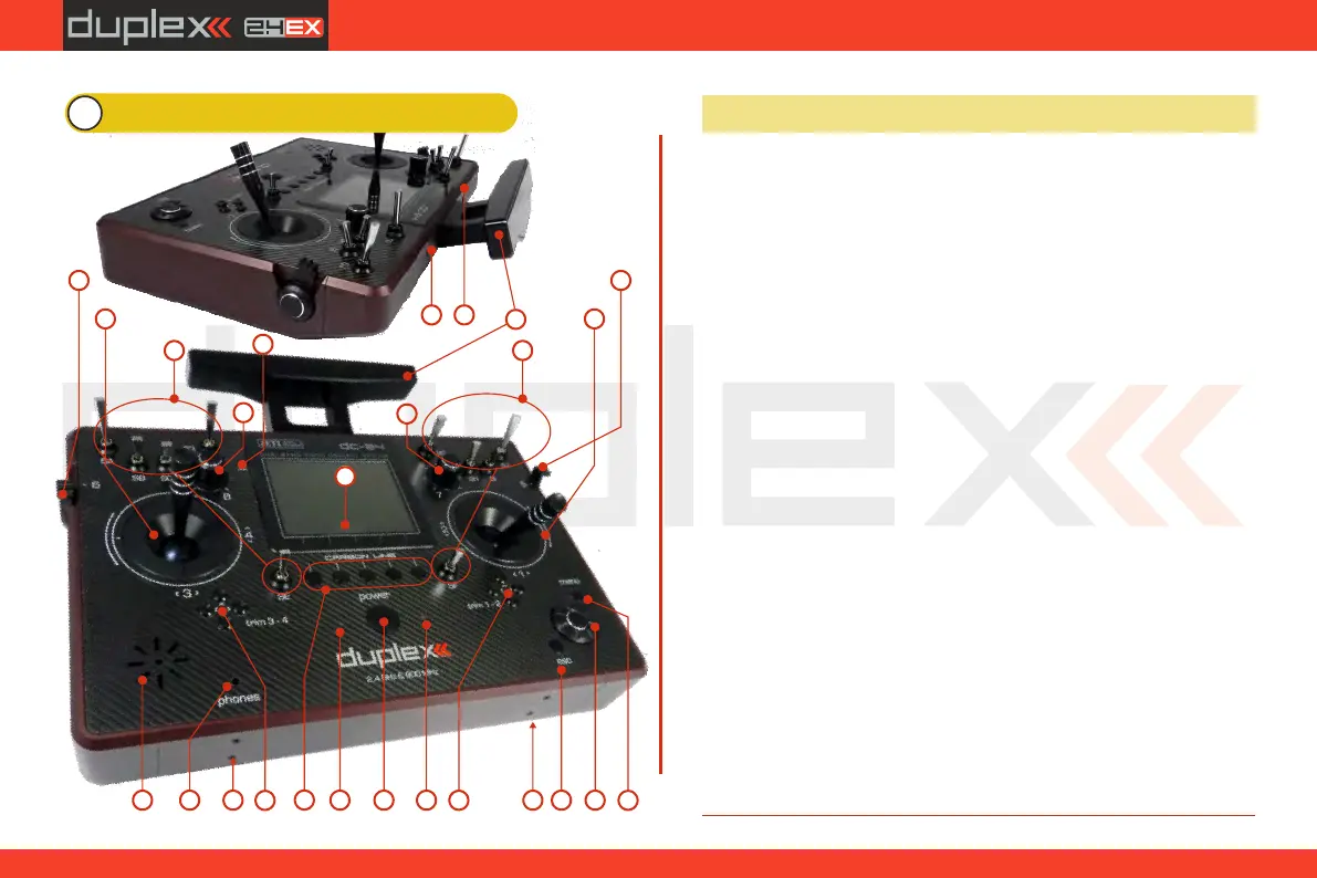
3 Description of Transmitter DC-24
1. Right Stick 1, 2 – the DC-24 Transmitter Supports Modes 1-4, see
Control Sticks -> mode change
2. Left Stick 3, 4 the DC-24 Transmitter Supports Modes 1-4, see
Control Sticks -> mode change
3. Swappable and Assignable Switches: Sa, Sb, Sc, Sd, Se, Sf, Sg, Sh, Si, Sj
4. Digital Trims for the Left Stick T3, T4
5. Digital Trims for the Right Stick T1, T2
6. Right Side Control Lever 5
7. Left Side Control Lever 6
8. Rotary Control Knob 7
9. Rotary Control Knob 8
10. LCD Display
11. Function Buttons F1 – F5
12. Transmitter On/Off Power Switch
13. 3D Control Selector
14. Menu Button
15. ESC Button
16. Antenna/ Transmitter Handle
17. Charge Jack
18. USB PC Interface
19. Earphone Jack
20. ON/OFF & Charging LED Indicators
21. Speaker
22. Harness Bracket (optional accessory) Installation Holes
23. Microphone
3.1. Control Identification
3
1
2
3
4
5
67
8
9
11
12
13
15
14
16
17
18
1921
2020
22 22
10
23
12