EasyManua.ls Logo

JIYI K3-A - Page 7

Default Icon
32 pages
Print Icon
To Next Page IconTo Next Page
To Previous Page IconTo Previous Page
Loading...
JIYI Robotics CO. Ltd
7
The port definitions of K3A is showing in the following table:
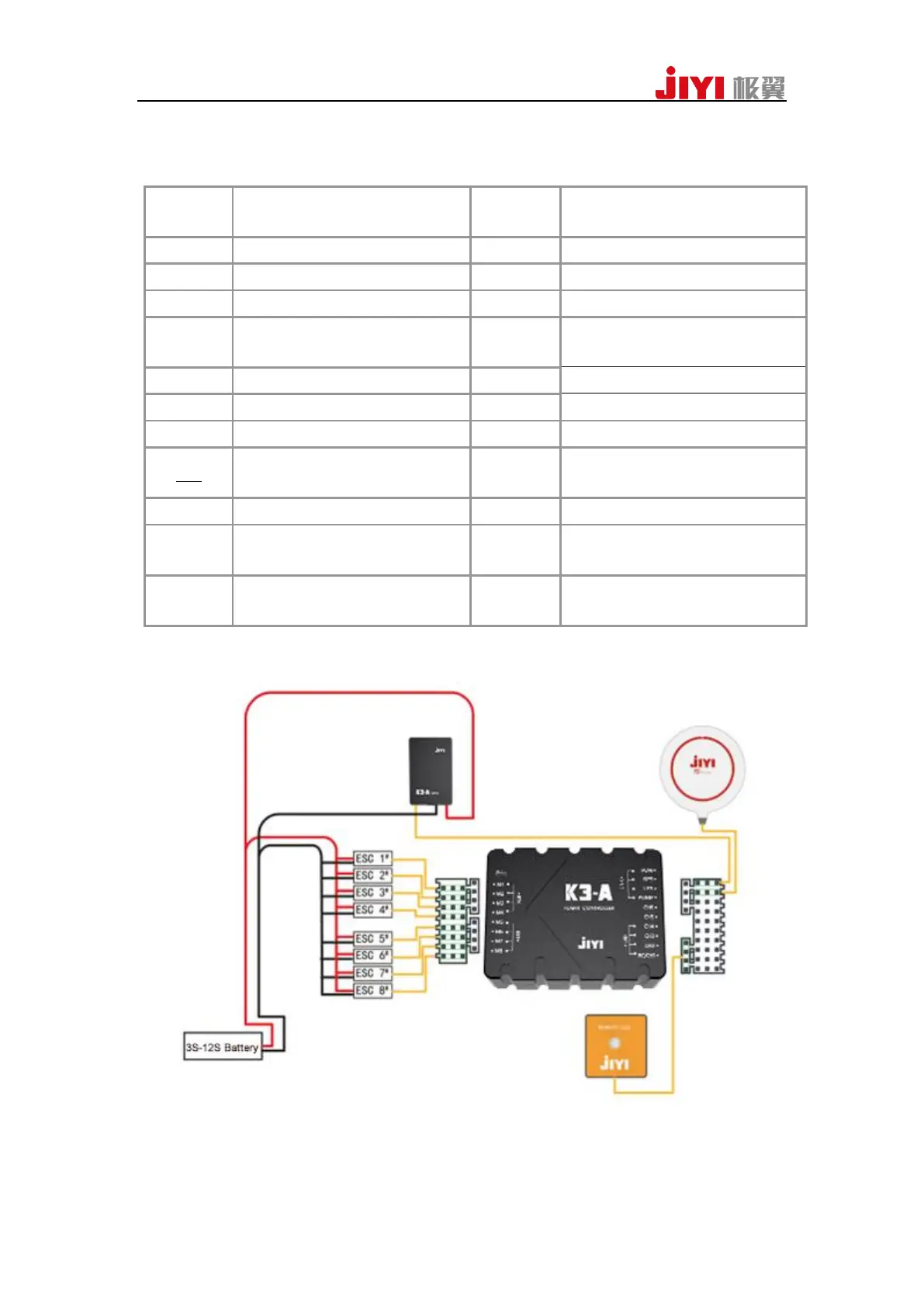
2Overall Wiring Diagram
M1
Connects to ESC 1
#
POW
Connects to power management
module
M2
Connects to ESC 2
#
GPS
Connects to GPS module
M3
Connects to ESC 3
#
LFS
Connects to flow sensor
M4
Connects to ESC 4
#
PUMP
Communicates to water pump
M5
Connects to ESC 5
#
CH6
Communicates to the second
water pump
M6
Connects to ESC 6
#
CH5
PWM output, controlled by OUT2
M7
Connects to ESC 7
#
CH4
PWM output, controlled by OUT1
M8
Connects to ESC 8
#
CH3
Connects to switchlevel meter
RTK
Connects to GPS2 module or RTK
module
CH2
Connects to percentage level
meter
EXT
Connects to radar module
RC/CH1
Connects to PPM/SBUS receiver
LINK
Use USB to connects to Assistant2
or use datalink to connect to APP
LED
Connects to LED tricolored light
module

Related product manuals