EasyManua.ls Logo

JL Audio JX360/2 User Manual

JL Audio JX360/2
17 pages
To Next Page IconTo Next Page
Page #1 background imageLoading...
Page #1 background image
Thank you for purchasing a JL Audio amplifier for
your automotive sound system.
Your amplifier has been designed and manufactured to exacting
standards in order to ensure years of musical enjoyment in your vehicle.
For maximum performance, we highly recommend that you have
your new amplifier installed by an authorized JL Audio dealer. Your
authorized dealer has the training, expertise and installation equipment
to ensure optimum performance from this product. Should you
decide to install the amplifier yourself, please take the time
to read this manual thoroughly so as to familiarize yourself
with its installation requirements and setup procedures.
If you have any questions regarding the instructions in this
manual or any aspect of your amplifier’s operation, please contact your
authorized JL Audio dealer for assistance. If you need further assistance,
please call our Technical Support Department
at (954) 443-1100 during business hours.
OWNER’S MANUAL
360W 2-Channel, Full-Range Amplifier

Other manuals for JL Audio JX360/2

Question and Answer IconNeed help?

Do you have a question about the JL Audio JX360/2 and is the answer not in the manual?

JL Audio JX360/2 Specifications

General IconGeneral
Amplifier classA/B
High pass filterYes
RMS output power (max)360 W
Number of amplifier channels2 channels
RMS power output per channel (2 Ohm)140 W
RMS power output per channel (4 Ohm)90 W
Maximum power output per channel (4 Ohm)110 W
Weight and Dimensions IconWeight and Dimensions
Depth195 mm
Width348 mm
Height53 mm
Weight3450 g

Summary

SERIAL NUMBER

Protect Your Hearing!

Warning to limit exposure to high sound pressure levels to prevent hearing damage.

INSTALLATION APPLICATIONS

PLANNING YOUR INSTALLATION

Cooling Efficiency Considerations

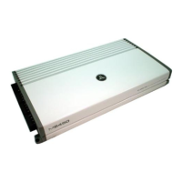
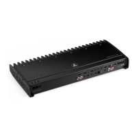
Ensure amplifier shell has ample air exposure for optimum cooling performance.

Safety Considerations

Install in dry, ventilated area, secure unit, avoid interfering with safety equipment.

Stupid Mistakes to Avoid

Avoid drilling vital systems, running wires externally, or exposing circuits to elements.

PRODUCT DESCRIPTION

TYPICAL INSTALLATION SEQUENCE

POWER CONNECTIONS

Fuse Requirements

Install appropriate fuse (50A) within 18 inches of battery post for vehicle safety.

TURN-ON LEAD

INPUT SECTIONS

Low-Level Inputs

Use RCA jacks for preamp level signal input; preferred method.

INPUT SENSITIVITY CONTROL

FILTER CONTROLS

Filter Mode Control

Select High-Pass (HP), Off, or Low-Pass (LP) filter to attenuate specific frequencies.

Filter Freq. (Hz)

Adjusts cutoff frequency (50-200 Hz) for selected filter mode.

PREOUTS

SPEAKER OUTPUTS

BRIDGING CONSIDERATIONS

Left Channel Only or Right Channel Only Information

Use Y-adapter for mono signal to drive single channel speakers.

Left + Right Channel Information

Stereo input automatically sums to mono for subwoofer or center channel.

AMPLIFIER STATUS INDICATOR LIGHTS & PROTECTION CIRCUITRY

Power Indicator

Green light indicates amplifier is on and operating normally.

Protect Indicator

Red light indicates protection mode activated due to overload, short-circuit, or low impedance.

SERVICING YOUR AMPLIFIER

Input Sensitivity Level Setting

JX360/2 Specifications

TROUBLESHOOTING

Input Sensitivity Setting

Set input sensitivity for maximum low-distortion output.

Amplifier Not Turning On

Check fuse, connections, and +12V at remote terminal.
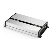
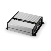
INSTALLATION NOTES

LIMITED WARRANTY - AMPLIFIERS (USA)

Related product manuals