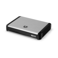
8 | JL Audio - RD400/4 Owner’s Manual
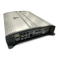
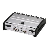
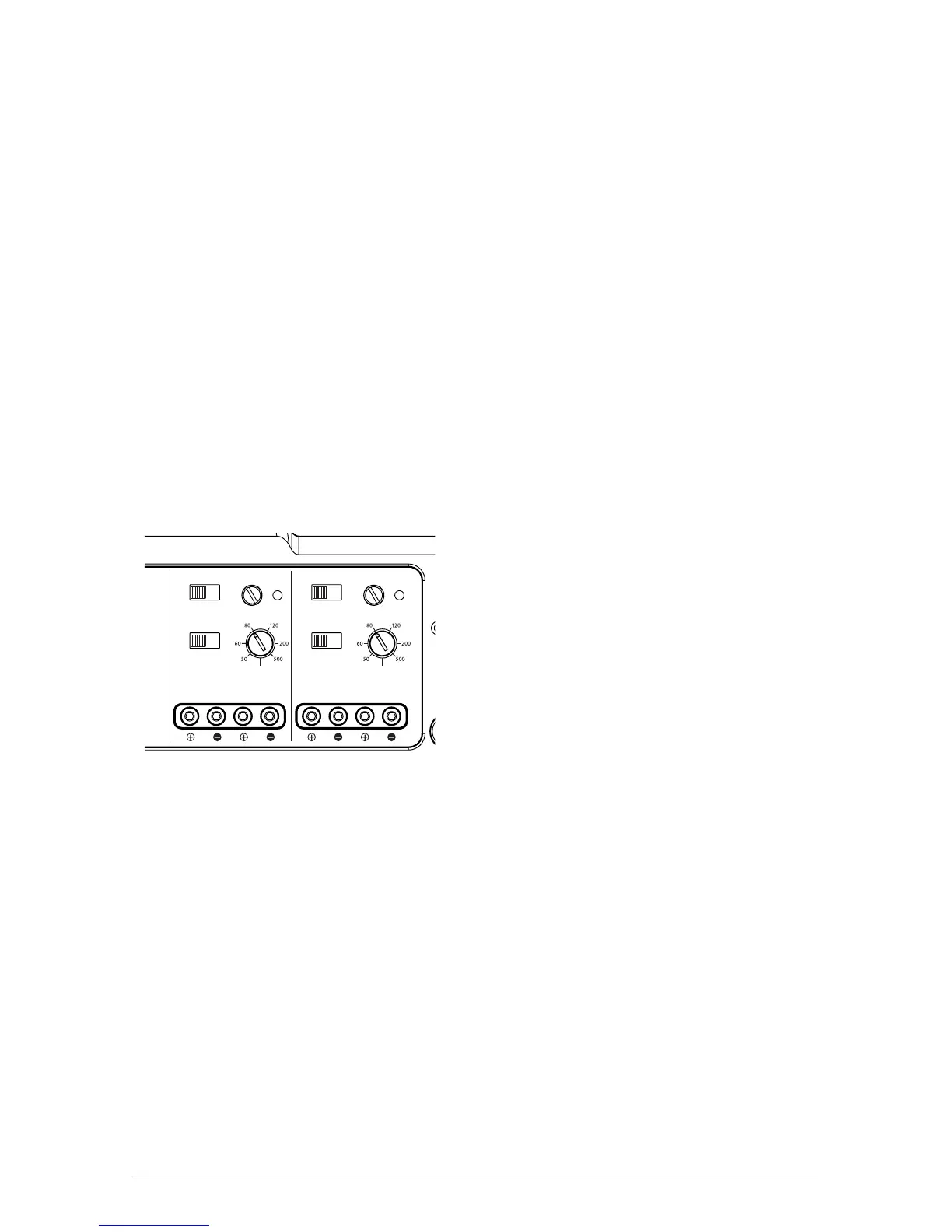
INPUT SENSITIVITY CONTROLS
The control labeled “Input Sensitivity” and
“Clipping” LED are used to match the source
unit’s output voltage to the input stage of the
RD400/4 for maximum clean output. Rotating the
control clockwise will result in higher sensitivity
(louder for a given input voltage). Rotating the
control counter-clockwise will result in lower
sensitivity (quieter for a given input voltage).
To properly set the amplifier for maximum
clean output, please refer to Appendix A (page
14) in this manual. After using this procedure,
you can then adjust the “Input Sensitivity”
levels downward if this is required to achieve the
desired system balance.
Do not increase any “Input Sensitivity”
setting for any channel(s) of any amplifier in the
system beyond the maximum level established
during the procedure outlined in Appendix
A (page 14). Doing so will result in audible
distortion and possible speaker damage.
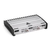
CHANNELS 3 & 4
Clipping
Clipping
FILTER CONTROLS
Most speakers are not designed to reproduce
the full range of frequencies audible by the human
ear. For this reason, most speaker systems are
comprised of multiple speakers, each dedicated
to reproducing a specific frequency range. Filters
are used to select which frequency range is sent
to each section of a speaker system. The division
of frequency ranges to different speakers can be
done with passive filters (coils and/or capacitors
between the amplifier outputs and the speakers),
which are acceptable and commonly used
for filtering between mid-range speakers and
tweeters. Filtering between subwoofer systems
and satellite speaker systems is best done with
active filters, which cut off frequency content at
the input to the amplifier. Active filters are more
stable than passive filters and do not introduce
extraneous resistance, which can degrade
subwoofer performance.
The active filter built into each channel
section of the RD400/4 can be used to eliminate
potentially harmful and/or undesired frequencies
from making their way through the amplifier
sections to the speaker(s). This serves to improve
tonal balance and to avoid distortion and possible
speaker failure. Correct use of these filters can
substantially increase the longevity and fidelity of
your audio system.
1) “Filter Mode” Controls: The RD400/4
employs 12 dB per octave filters for each
pair of channels. Each of these filters can be
controlled or defeated completely by way of the
three-position “Filter Mode” switches in each
Channel Section:
“Off”: Defeats the filter completely, allowing
the full range of frequencies present at the
inputs to feed these channels. This is useful for
systems utilizing outboard active crossovers
or requiring full-range reproduction from this
channel pair.
“LP” (Low-Pass): Configures the filter to
attenuate frequencies above the indicated filter
frequency, at a rate of 12 dB per octave. This
is useful for connection of subwoofers to one
or more of the RD400/4’s channel pairs in a
bi-amplified system.
“HP” (High-Pass): Configures the filter to
attenuate frequencies below the indicated filter
frequency at a rate of 12 dB per octave. This is
useful for connection of component speakers
or coaxials to one or more of the RD400/4’s
channel pairs in a bi-amplified system.
2) “Filter Freq. (Hz)” The filter frequency
markings surrounding these rotary controls
(one in each Channel Section) are for reference
purposes and are generally accurate to within
1/3 octave or better.
 Loading...