113538-7 Telephone 01422 822282 25
Unregulated Gas Valve
Regulate (govern) gas externally (refer to “Supply Pressure”
in chart on
page 23) to the correct gas pressure for the gas
being used. Operate dryer through one complete cycle to
ensure proper operation.
Regulated Gas Valve
Refer to “Gas Pressure Adjustment” on this page to adjust
the gas valve to the appropriate burner pressure listed on
page 23. The supply pressure must also match what is listed
on page 23 for the type of gas to be used.
IMPORTANT: Conversions done improperly can result in a
fire or explosion!
Gas Pressure Adjustment
Disconnect electrical power to the dryer.
To adjust gas valve’s internal regulator, remove the regulator
cap with a screwdriver. Once cap is removed, a small
screwdriver can be used to turn the plastic adjustment screw
in the valve. Turn the screw clockwise to raise pressure and
counterclockwise to lower pressure.
Gas (burner) pressure is measured with the burner in operation
for all burner adjustment conditions. Therefore once the
necessary adjustments have been made, the dryer must be
operated in a heating cycle to verify that the pressure is correct.
Reconnect the electrical power and run the dryer. If the
pressure is not correct, you must discontinue the power to
the unit and make further adjustments. Repeat these steps
as many times as necessary to achieve the correct burner
pressure. Once the adjustment of the valve is complete, the
regulator cap must be replaced and sealed with, for example,
paint to prevent maladjustment by the user.
!
WARNING
This appliance must only be operated with the gas
type indicated on the dryer’s rating plate. If the
appliance is converted (gas type changed), a new
rating plate must be obtained from JLA Limited.
Conversions done improperly can result in a fire or
explosion!
Gas Pressure Testing _________________
For proper operation, the gas pressure must be correct,
consistent and maintained at the gas pressure rates shown
on
page 23. Provisions are made at the gas valve for taking
gas pressure readings.
There are 2 types of devices used to measure gas pressure.
They are the spring/mechanical type gauge and the
manometer. The use of the spring/mechanical type gauge is
not recommended because they are very easily damaged and
are not always accurate. The preferred type of gauge is the
manometer because it is a simple device to use and is highly
accurate. A manometer is simply a glass or transparent plastic
tube with a scale graduated in inches or mb. When it is filled
with water and pressure is applied, the water in the tube rises,
showing the exact gas pressure.
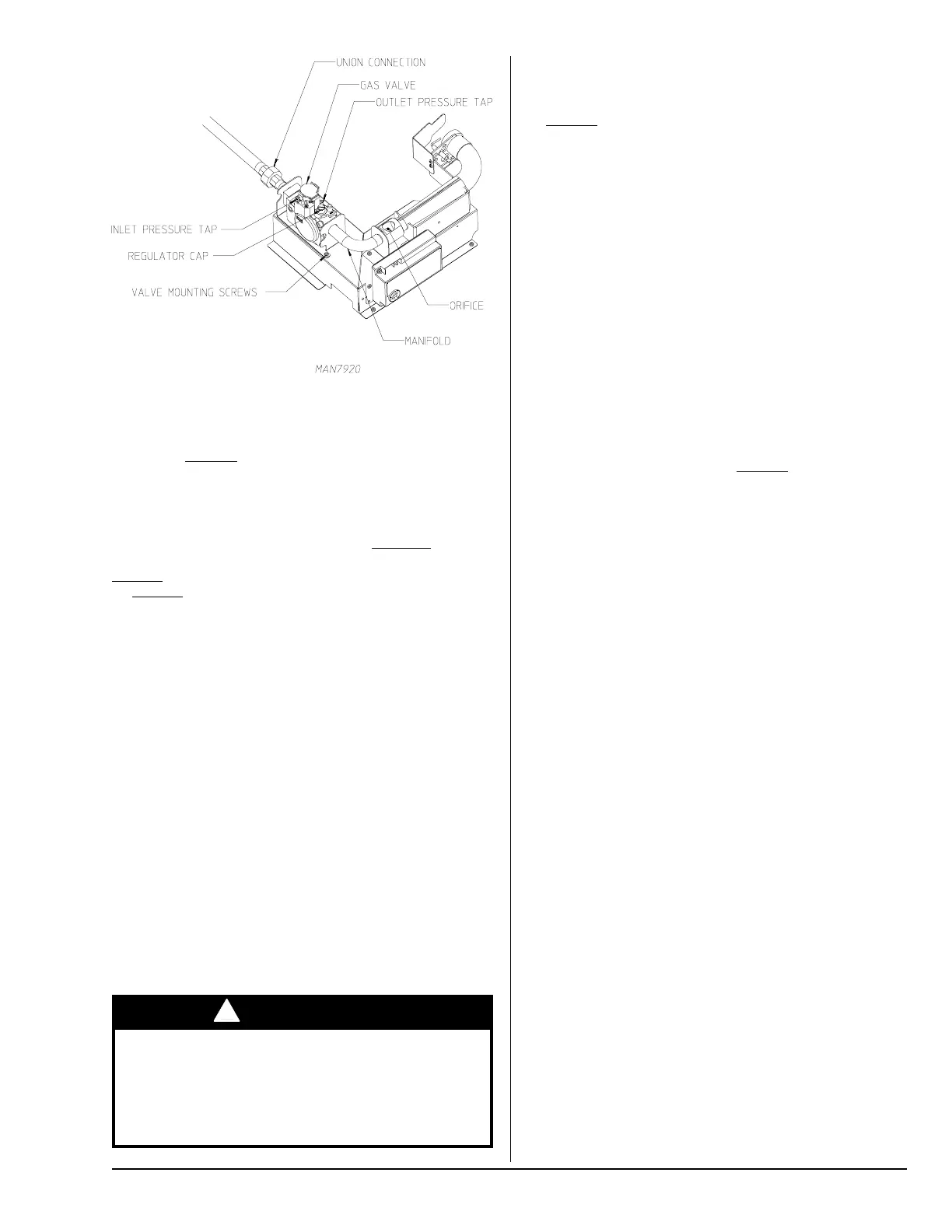
Gas Pressure Test Procedure
Turn gas cock in gas supply line to “OFF” position.
Back out miniature screw inside pressure tap and attach
manometer (refer to the illustration on this page).
Turn gas cock to “ON” position.
Start the dryer in Heat Mode and wait for ignition. Gas manifold
pressure should be as shown on
page 23.
If the gas pressure needs to be adjusted, refer to “Gas
Pressure Adjustment” on this page.
Once test is complete, turn gas cock to “OFF” position.
Remove manometer. Tighten screw inside the pressure tap
or install plug.
Turn gas cock to “ON” position and check for leaks with soap
solution with main burner “ON.”
Water Information _____________________
Before You Start
Check Local Codes and Permits
Call your local water company or the proper municipal authority
for information regarding local codes.
IMPORTANT: It is your responsibility to have all plumbing
connections made by a qualified professional to ensure that
the plumbing installation is adequate and conforms to local,
state, and federal regulations or codes.
It is the installer’s or owner’s responsibility to see that the
required water pressure, pipe size, or connections are
provided. The manufacturer assumes no responsibility if
the fire suppression system is not connected, installed, or
maintained properly.
Installation
Water Supply
The fire suppression system must be supplied with a minimum
water pipe size of 1/2-inch (12.7 mm) and be provided with 40
psi +/- 20 psi (2.75 bar +/- 1.37 bar) of pressure.
If the rear area of the dryer or the water supply is located in
an area where it will be exposed to cold/freezing temperatures,
provisions must be made to protect these water lines from
freezing.