Do you have a question about the JLG 4045R and is the answer not in the manual?
General safety precautions for operating and maintaining the Mobile Elevating Work Platform (MEWP).
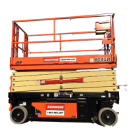
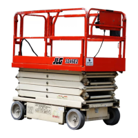
Details operating specifications for the 4045R model, including platform, driving, and chassis data.
Explains the function of tilt alarm and high drive speed cutout limit switches.
Provides information on lubrication capacities and hydraulic oil types and specifications.
Lists hydraulic pressure settings for main, lift, and steer relief valves.
Details specifications for lift and steer cylinders, including bore diameter and stroke.
Indicates the location of the serial number plate for machine identification.
Lists critical stability weights for components like batteries and wheel assemblies.
Provides weights for major machine components like platform and arm assembly.
Details torque requirements for fasteners and refers to torque charts.
Outlines essential information for operating and maintaining the machine safely and efficiently.
Details scheduled inspections and maintenance tasks based on intervals and codes.
Describes key components requiring service, such as scissor arm safety props.
Provides general guidelines for servicing, including safety, cleanliness, and component handling.
Covers lubrication requirements, hydraulic oil, and changing procedures.
Explains the procedure for measuring acceptable cylinder drift.
Offers guidelines for repairing pins and composite bearings.
Identifies components located in the left and right side compartments.
Details procedures for removing, maintaining, and disconnecting batteries.
Explains battery charging procedures for different charger types and safety precautions.
Provides instructions for installing an optional DC/AC power inverter.
Guides on accessing, removing, and installing the logic control module.
Locates and describes the main power contactor relay and pump control module.
Details removal and installation procedures for the pump control module.
Covers component location, removal, and installation for the folding ground control station.
Covers component location, removal, and installation for the fixed ground control station.
Overviews control station components and provides installation/removal instructions.
Guides on removing and installing the tilt sensor and its wiring.
Explains the function and installation of the elevation sensor.
Details components and adjustment procedures for the Pot-Hole Protection System.
Illustrates steer and spindle assembly installation and related components.
Provides instructions for positioning and supporting arms and platform.
Outlines procedures for safely removing the platform.
Details methods for removing scissor arm assemblies.
Explains the principles of double-acting and single-acting hydraulic cylinders.
Describes the function of various hydraulic valves like solenoid, relief, and proportional valves.
Explains pump motor operation, electrical evaluation, and troubleshooting.
Provides instructions and diagrams for installing the hydraulic tank.
Details the removal, disassembly, assembly, and installation of the hydraulic pump/motor.
Guides on installing the hydraulic manifold valve assembly and its schematic.
Provides instructions for installing the hydraulic drive motor.
Explains the installation and manual disengagement of hydraulic brakes.
Details the process for setting hydraulic pressure relief valves using an analyzer.
Describes how to check cylinders for proper operation and leakage.
Outlines the procedure for removing and installing the lift cylinder.
Provides disassembly and assembly steps for the lower lift cylinder.
Provides disassembly and assembly steps for the upper lift cylinder.
Offers general procedures for cylinder repair, including disassembly and cleaning.
Introduces the hand-held analyzer, its display, controls, and connection procedure.
Details the procedure for calibrating the joystick if it is replaced.
Explains how to calibrate the tilt sensor and troubleshoot common issues.
Guides on calibrating the elevation sensor and its relation to LSS.
Provides instructions for updating the power control module software.
Lists machine configuration settings and their default values.
Explains how to adjust machine model and personality settings for optimal performance.
Explains how the Load Sensing System measures load and prevents overload situations.
Details the analyzer's personalities and diagnostic menus for LSS.
Outlines necessary preparations before performing LSS calibration.
Provides procedures for empty, loaded platform, and LSS verification calibrations.
Describes how to test the LSS functionality with specific load conditions.
Lists pin assignments for LSS pressure transducers.
Offers possible resolutions for common LSS calibration and operation issues.
Introduces diagnostic trouble codes (DTCs) and how they are indicated.
Explains DTC sorting and troubleshooting approach.
Provides tables listing DTCs, their messages, actions, and triggers.
Introduces schematics for locating and correcting operating problems.
Covers multimeter usage, grounding, backprobing, polarity, and scale.
Details the application of dielectric compound to AMP connectors.
Provides installation and removal instructions for Deutsch DT/DTP and HD30/HDP20 series connectors.
Explains basic checks for switches and limit switches.
Contains electrical schematic diagrams for various machine systems.
Includes hydraulic schematic diagrams for system analysis.
| Platform Capacity | 705 lb / 320 kg |
|---|---|
| Weight | 7, 500 lb / 3, 402 kg |
| Drive Speed | 3.5 mph |
| Gradeability | 25% |
| Power Source | Electric |
| Drive Speed - Elevated | 0.5 mph |
| Drive Speed - Lowered | 3.5 mph |
| Max Travel Speed | 3.5 mph |
| Platform Height | 40 ft |
| Working Height | 46 ft |
| Overall Length | 9.08 ft / 2.77 m |
| Maximum Working Height | 46 ft |
| Platform Length | 8 ft |
| Machine Length | 9.08 ft / 2.77 m |