SECTION 4 - BOOM & PLATFORM
3121160 – JLG Lift – 4-45
4.15 FOOT SWITCH ADJUSTMENT
Adjust so that functions will operate when pedal is at cen-
ter of travel. If switch operates within last 1/4 in. (6.35 mm)
of travel, top or bottom, it should be adjusted.
4.16 UPRIGHT MONITORING SYSTEM
The UMS provides a visual and audible warning to the
operator when the limits of the upright assembly align-
ment have been reached. In addition, the UMS will not
allow the tower boom to be lowered when the upright
assembly is misaligned in a direction oriented away from
the work platform.
Re-Synchronizing Upright
A pull type control valve allows the operator to adjust the
upright level cylinder if the upright is not 90° (vertical) rela-
tive to the chassis (Refer to Figure 4-20.). This valve is
located in the tank compartment area.
Perform the following steps with the aid of an assistant:
1. Turn the key switch to the ground control position.
2. Start the engine.
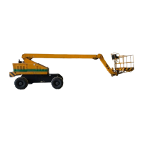
3. Pull and hold the red relevel knob located next to the
main control valve. Refer to Figure 4-19.
4. Raise the tower boom 6 feet (1.8 m).
5. Release the red relevel knob.
6. Lower the tower boom fully and continue to hold
down the switch to Tower Down for an additional 20
seconds.
7. Repeat steps 3 thru 6 as necessary until the upright
is 90° (vertical) relative to the chassis.
Table 4-2. Ramp Current Setting Range.
FUNCTION
MINIMUM
CURRENT
MAXIMUM
CURRENT
MAIN LIFT UP 450 to 550 mA ‘1300 to 1500 mA
MAIN LIFT DOWN 450 to 550 mA 1700 to 2000 mA
(Set 450 mA higher
than Main lift)
SWING RIGHT 450 to 550 mA 1000 to 1300 mA
SWING LEFT 450 to 550 mA 1100 to 1300 mA
(Set 100 mA higher
than swing right)
FLOW CONTROL 750 to 850 mA 1100 to 1300M A
(Set using Main Tele)
DRIVE FORWARD 20 to 60 mA 130 to 160 mA
DRIVE REVERSE 20 to 60 mA 130 to 160 mA
Table 4-3. Ramp time Setting.
FUNCTION RAMP TIME
Lift Up
Ramp UpTime = 5:00 sec.
Ramp Down Time = 3:00 sec.
Lift Down
Ramp Up Time =5:00 sec.
Ra mp Down T ime =3: 00 sec .
Swing Right
Ramp Up Time =7:00 sec.
Ra mp Down T ime =3: 00 sec .
Swing Left
Ramp Up Time =7:00 sec.
Ra mp Down T ime =3: 00 sec .
Drive Forward
Ramp Up Time =4:30 sec.
Ramp Down Time = 2:30 sec.
Drive Reverse
Ramp Up Time = 4:30 sec.
Ramp Down Time = 2:00 sec.
Flow Control
Ramp Up Time =3:00 sec.
Ra mp Down T ime =0. 00 sec .
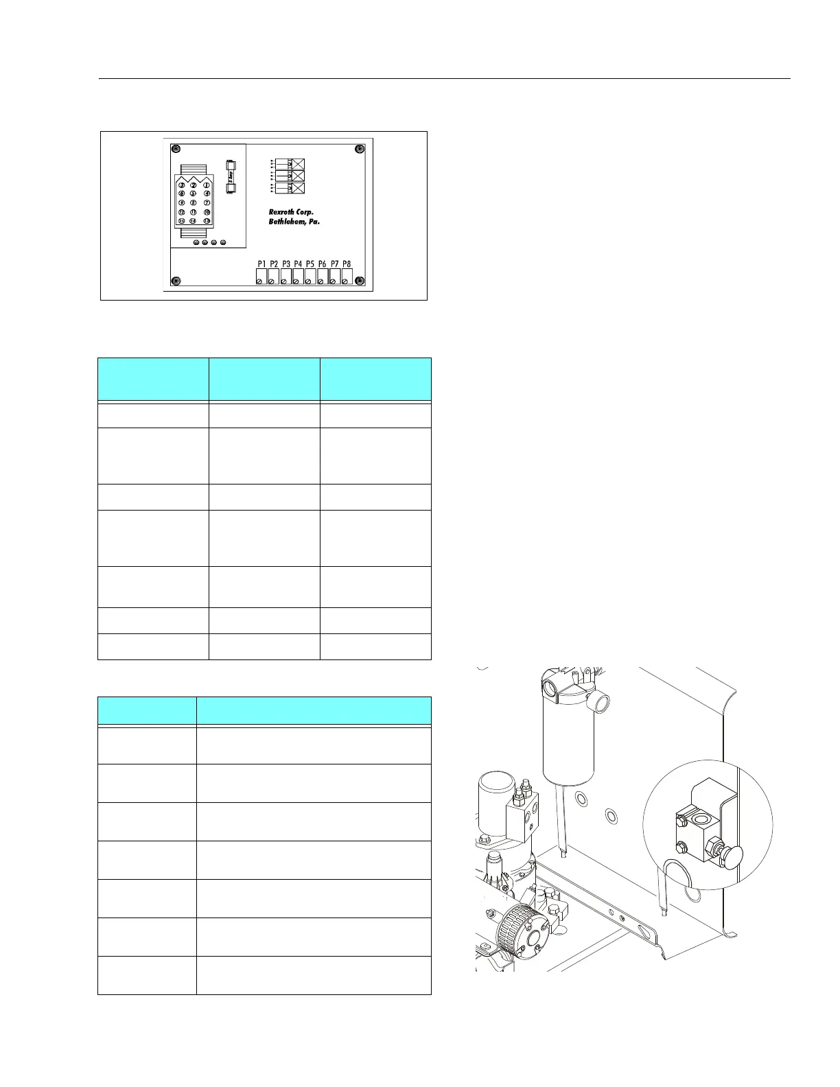
Figure 4-18. Control Card
Figure 4-19. Releveling Valve