EasyManua.ls Logo

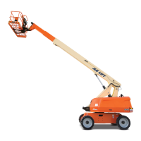
JLG 660SJ Service Manual

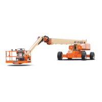
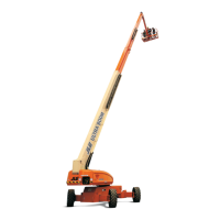
JLG 660SJ
334 pages
To Next Page IconTo Next Page
Page #1 background imageLoading...
Page #1 background image
Service and Maintenance Manual
Models
600S
600SJ
660SJ
S/N 0300080000
to 0300171769
P/N - 3121202
February 26, 2014

Table of Contents

Other manuals for JLG 660SJ

Questions and Answers:

JLG 660SJ Specifications

General IconGeneral
Platform Height66 ft
Working Height72 ft
Platform Capacity - Unrestricted500 lbs
Machine Width8 ft 2 in
Machine Height9 ft 10 in
Drive Speed - 4WD3.5 mph
Gradeability - 4WD45%
Engine TypeDiesel
Swing360° Continuous
Platform Rotator180°
Ground Clearance1 ft
Fuel Tank Capacity30 gal
Maximum Platform Height66 ft
Engine Power74 hp
Drive Speed3.5 mph
Platform Capacity - Restricted750 lbs
Platform Capacity500 lbs

Summary

SECTION A - INTRODUCTION - MAINTENANCE SAFETY PRECAUTIONS

A GENERAL

General safety precautions for aerial platform maintenance.

B HYDRAULIC SYSTEM SAFETY

Safety precautions for high-pressure hydraulic systems.

C MAINTENANCE

General safety guidelines and warnings for maintenance tasks.

SECTION 1 - SPECIFICATIONS

1.1 CAPACITIES

Details fluid capacities for various machine systems.

1.2 COMPONENT DATA

Provides technical data for engine and other components.

1.6 LUBRICATION

Details lubrication specifications for various components and intervals.

1.7 PRESSURE SETTINGS

Lists hydraulic system pressure settings for various functions.

1.10 CRITICAL STABILITY WEIGHTS

Lists critical weights essential for machine stability and safety.

1.11 LUBRICATION AND OPERATOR MAINTENANCE

Outlines lubrication points, specifications, and maintenance intervals.

SECTION 2 - GENERAL

2.1 MACHINE PREPARATION, INSPECTION, AND MAINTENANCE

Covers general guidelines for machine readiness, inspections, and maintenance programs.

2.2 SERVICE AND GUIDELINES

Provides general information on servicing, safety, and component handling.

SECTION 3 - CHASSIS & TURNTABLE

3.1 TIRES & WHEELS

Covers tire inflation, damage, replacement, and wheel installation procedures.

3.2 DRIVE TORQUE HUB

Details roll, leak, and brake testing, and tightening/torquing bolts.

3.8 SWING BEARING

Details turntable bearing mounting bolt checks and wear tolerances.

3.9 SWING BRAKE - MICO

Covers disassembly, inspection, and assembly of the swing brake.

3.10 ROTARY COUPLING

Procedure for installing the seal kit for the rotary coupling.

3.11 GENERATOR

Maintenance schedule for the generator brushes and slip rings.

SECTION 4 - BOOM & PLATFORM

4.1 BOOM ROPE TORQUING PROCEDURES

Details the procedure for torquing boom rope adjusting nuts.

4.2 WEAR PADS

Covers wear pad inspection and replacement for the main boom.

4.3 WIRE ROPE

Provides daily inspection procedures and criteria for wire rope replacement.

4.4 BOOM MAINTENANCE

Covers removal procedures for platform support, rotator, slave cylinder, and powertrack.

4.5 ARTICULATING JIB BOOM

Details removal, disassembly, inspection, and assembly of the articulating jib boom.

4.6 LIMIT SWITCHES AND CAM VALVE ADJUSTMENT

Instructions for adjusting limit switches and cam valves.

SECTION 5 - HYDRAULICS

5.1 CYLINDERS - THEORY OF OPERATION

Explains the operation of double-acting and holding valve cylinders.

5.2 CYLINDER CHECKING PROCEDURE

Outlines procedures for checking cylinders with and without counterbalance valves.

5.3 CYLINDER REMOVAL AND INSTALLATION

Details removal and installation procedures for main boom telescope and lift cylinders.

5.7 PRESSURE SETTING PROCEDURES

Details procedures for setting hydraulic system pressures for various functions.

5.8 HYDRAULIC COMPONENT START-UP PROCEDURES AND RECOMMENDATIONS

Provides guidelines for starting up hydraulic components after installation or replacement.

SECTION 6 - JLG CONTROL SYSTEM

6.1 INTRODUCTION

Introduces the JLG Control System, its benefits, and analyzer usage.

6.3 USING THE ANALYZER

Explains how to navigate and interpret the analyzer display and menus.

6.5 ADJUSTING PARAMETERS USING THE HAND HELD ANALYZER

Guide on adjusting personality settings and parameters via the analyzer.

6.8 MACHINE PERSONALITY SETTINGS

Details personality ranges and default settings for various machine functions.

SECTION 7 - BASIC ELECTRICAL INFORMATION & SCHEMATICS

7.2 MULTIMETER BASICS

Explains basic multimeter usage: grounding, backprobing, min/max, polarity, scale, voltage/resistance.

7.3 APPLYING SILICONE DIELECTRIC COMPOUND TO ELECTRICAL CONNECTIONS

Details the procedure and reasons for applying silicone dielectric compound to electrical connections.

7.4 AMP CONNECTOR

Covers applying silicone dielectric compound and assembly/disassembly of AMP connectors.

7.5 DEUTSCH CONNECTORS

Procedures for DT/DTP and HD30/HDP series Deutsch connector assembly and disassembly.

Related product manuals