Do you have a question about the JLG 15MVL Series and is the answer not in the manual?
General safety precautions for maintenance.
Safety guidelines specific to the hydraulic system.
General safety practices during maintenance tasks.
Details system voltage, hydraulic system, and gearbox oil capacity.
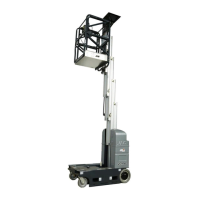
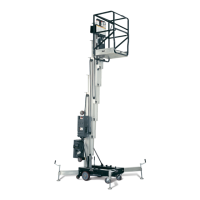
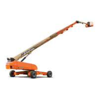
Lists key machine components and their specifications.
Provides platform capacities and load specifications.
Covers hydraulic oil types and lubrication specifications.
Specifies correct torque values for fasteners.
Outlines procedures for preparing, inspecting, and maintaining the machine.
Details scheduled maintenance and inspection tasks.
Provides general guidelines for servicing and maintenance.
Covers hydraulic system, oil types, and lubrication specifications.
Illustrates and lists base components.
Covers installation of drive motor and battery charger covers.
Details installation of the cut-out switch.
Includes tire wear, wheel replacement, and installation.
Covers roll and leak testing, oil, and brush wear warnings.
Step-by-step guide for removing the drive assembly.
Instructions for replacing drive motor brushes.
Step-by-step guide for disassembling the gearbox.
Covers hub disassembly steps.
Provides instructions for spindle disassembly.
Provides steps for main gearbox sub-assembly.
Details assembly of the motor, brake, and gearbox.
Covers the pot hole protection system components and installation.
Covers battery charger general info, maintenance, and indicators.
Details battery charger removal and installation.
Provides an overview of control component locations.
Covers installation of battery cover doors and lower covers.
Details installation of Ground Control Module and Traction Control Module.
Covers installation of the platform control console.
Covers battery replacement and condition testing.
Explains the battery disconnect option.
Details installation of 12V batteries.
Details installation of 4-6V batteries.
Covers service procedures for the ground control module.
Details programming of the ground control module.
Covers service procedures for the platform control console.
Covers pump-motor assembly service, including pressure settings.
Details service for the obstruction sensor system.
Lists and illustrates mast components.
Covers adjustment of mast chains and sequencing cables.
Details replacement of sequence cables.
Explains use of a special tool for hydraulic line disconnection.
Covers removal, inspection, and rebuild of the hydraulic lift cylinder.
Provides steps for cylinder disassembly.
Details inspection of cylinder rod, head, piston, and tube.
Instructions for assembling the cylinder.
Details cylinder installation.
Covers mast removal and installation.
Details mast assembly and disassembly procedures.
Covers installation of the MSP stockpicker platform.
Details mid-gate interlock installation for MSP.
Covers mast beacon installation.
Details gate alarm installation for specific platforms.
Covers installation of the height limiting switch.
Provides general troubleshooting guidance and warnings.
Explains how to use troubleshooting tables.
Guides on checking hydraulic circuits.
Guides on checking electrical circuits.
Provides basic multimeter usage for troubleshooting.
Covers testing of basic, limit, and automatic switches.
Explains the LCD display symbols and indicators.
Lists fault codes displayed on the LCD.
Index for fault code troubleshooting tables.
Contains component specifications.
Lists special tools for electrical connectors.
Details troubleshooting for specific fault codes.
Troubleshooting for main power circuit issues.
Troubleshooting for mast-related issues.
Addresses hydraulic leaks.
Troubleshooting for base frame components.
Troubleshooting for drive system issues.
| Working Height | 15.24 m |
|---|---|
| Horizontal Outreach | 7.62 m |
| Maximum Horizontal Reach | 7.62 m |
| Weight | 4, 853 kg |
| Power Source | Electric |
| Platform Dimensions | 0.76 m |