Do you have a question about the JLG 340AJ and is the answer not in the manual?
Contains general safety precautions for aerial platform maintenance to avoid injury or damage.
Highlights the high pressures in hydraulic systems and safety measures.
Lists safety precautions to be observed during maintenance.
Details operational specifications including capacity, travel grade, speed, and system voltage.
Provides key dimensions like turning radius, height, length, and width.
Lists capacities for hydraulic oil, drive hub lubricant, and engine coolant.
Specifies engine details such as cylinders, bore, stroke, displacement, and RPMs.
Outlines function speeds and tolerances for various operations.
Details lubrication specifications and intervals for machine components.
Covers general information on preparing, inspecting, and maintaining the machine for safe operation.
Provides general information and guidelines for using servicing and maintenance procedures.
Details hydraulic system contamination, oil types, and lubrication specifications.
Provides critical safety instructions for welding on JLG equipment to prevent damage.
Guidelines for tire replacement, characteristics, and wheel installation.
Description of the drive system, including pump, motors, and flow dividers.
Detailed instructions for the disassembly and assembly of the drive motor.
Procedures for roll, leak, and brake testing, and bolt tightening for drive hubs.
Describes the swing motor and provides procedures for removal and installation.
Details the components, removal, and installation procedures for the swing drive assembly.
Explains the four engine operating states: Stopped, Cranking, Starting, and Running.
Lists the conditions required for the engine to start.
Provides details on the Kubota engine's oil pressure switch and speed sensor.
Describes the GM Dual Fuel engine's control system and fuel selection.
Explains the time-dependent enable circuit for platform controls.
Details the system that senses boom angles for high-speed travel conditions.
Provides procedures for the disassembly and assembly of the main boom.
Explains the theory of operation and disassembly/assembly of the rotary actuator.
Details procedures for lubricating O-rings in hydraulic fittings using cup/brush, dip, or spray methods.
Covers disassembly, assembly, general information, and inspection of hydraulic cylinders.
Description and diagrams of the Sauer-Danfoss H1 tandem closed circuit piston pumps.
Step-by-step instructions for setting relief valves for main, swing, steer, and platform level systems.
Introduction to the analyzer kit, its purpose, and the machine configuration process.
Details the seven levels of the analyzer menu structure for navigation and diagnostics.
Instructions on connecting the analyzer and navigating its menus for machine parameter adjustments.
Identifies and describes the function of ground and platform control switches and joysticks.
Outlines actions and checks performed during system startup for proper function.
Provides information on system fault messages, DTCs, and troubleshooting procedures.
Provides basic electrical information and schematics for troubleshooting operating problems.
Explains basic multimeter usage for circuit measurements like voltage, resistance, and continuity.
Details the procedure for applying dielectric grease to electrical connectors to prevent oxidation.
Provides assembly and disassembly instructions for AMP connectors.
Details assembly and disassembly procedures for DT/DTP and HD/HDP series Deutsch connectors.
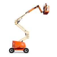
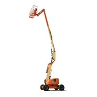
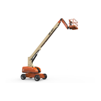
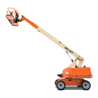
| Platform Height | 34 ft |
|---|---|
| Platform Capacity | 500 lb |
| Power Source | Diesel |
| Drive Speed - 4 Wheel Drive | 3.5 mph |
| Gradeability - 4 Wheel Drive | 45% |
| Turning Radius - Outside | 12 ft 6 in |
| Drive Speed | 3.5 mph |
| Platform Rotation | 180 Degrees |
| Ground Clearance | 12 in |
| Engine Type | Diesel |
| Swing | 355 Degrees Non-Continuous |