temperature range of the controller.
3 Use multiple copper core insulated conductors for installation. First, determine
the length of the wire. Ensuring the installation position, and to reduce the
electrical loss as much as possible, pay attention to select the wire specifications
as required.
4 Use a 4mm copper cable or more to connect the battery to the controller. Pat
attention for the positive and negative electrodes, not reverse.
5. After the above operations are completed, the two indicators on the panel of
the controller flash and the LCD screen lights up.
6 If the controller does not work properly, check whether the connection is
reversed and if the battery voltage reaches above 8V.
7. Select the appropriate copper core cable to connect the load to the controller.
Note that the positive and negative poles can be distinguished. If the positive and
negative poles are connected incorrectly, the load may be permanently damaged
because your load may not be protected against reverse polarity. This controller
can connect two loads as well, if there are two loads that need to be connected,
twist the positive terminals of the two loads together and connect them to the L+
terminal of the controller, and connect the negative terminal to the L1-, L2-
terminals of the controller. After connecting, observe whether the load is working
properly. If it is not working, observe whether the “out” indicator on the controller
panel is flashing. If it flashes, it indicates that the
8
battery is under voltage and it needs to be charged before it can work normally.
8. Connect the solar panel to the controller S+, S-. Note the polarity of the
positive and negative poles. If the pole is reversed, the controller will start reverse
polarity protection. If the connection is correct, the red LED on the controller
panel lights up (during daytime).
9. Connect the dump load to the controller, there is no distinction between
positive and negative poles.
10. Connect the fan and the controller. If it is a three-phase AC fan, the three
terminals have no distinction between positive and negative poles. If it is a DC
fan, connect any two of the three terminals on the fan side of the controller. Note:
When installing the fan, please make sure lower wind speed to avoid accidents.
4 - 2
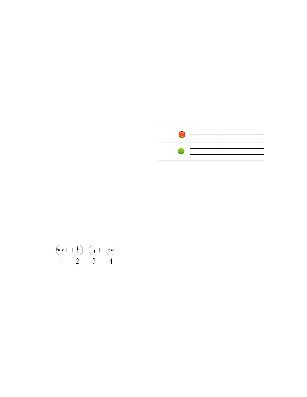
(2)Button description
4-2
As shown in figure 4-2,
Button①: Press this button to enter setup interface or switch program;
Button②: Click this button to switch down in first views page,in the setup
interface click this button is to increase the parameter values, step 0.1 V each.
9
Button③: Click this button to switch up browsing on page views,in the setup
interface click this button is used to decrease the parameter value, step 0.1 V
each.
Button④: Click this button to exit the setup interface, and save the parameters.
(3)LCD screen (the default interface)
After user setting, in accordance with the specifications, general entered into the
following interface automatically (figure 4-3) :
 Loading...