2 A19 Technical Bulletin
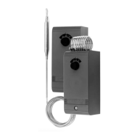
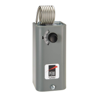
Fig. 2 -- Part No. FTG13A-600R
packing nut assembly. (Used with
swaged bulb with support tube for
direct immersion application.)
Fig. 3 -- Bulb well for liquid
immersion applications where a
temperature bulb may be removed
without draining tank.
Dial settings normally indicate the
cutout setting unless otherwise
specified by the equipment
manufacturer. Models with SPDT
contacts are normally set so the red
(common) to yellow contacts open
at the dial setting.
Models with adjustable differential
and ranges of 20/80°F (-5/28°C),
-30/50°F (-35/10°C) and -30/100°F
(-35/40°C) have a differential scale
plate showing increments of
differential. Other ranges have a
scale plate with a multiplier. For
example when “MIN” differential is
5F° (2.8C°) then x2 is 10F° (5.6C°),
x3 is 15F° (8.3C°), etc. The
controls are supplied with adjusting
lever at minimum differential
stamped on the control. To adjust
move the lever to the differential
required.
Low cutout or high cutout stop
supplied on certain models
(specified by the equipment
manufacturer).
Fig. 4 -- Terminal arrangement of
SPDT models.
If high or low cutout stop adjustment
is required proceed as follows:
1. Set dial to temperature at
which stop is desired.
2. Remove cover of the control.
3. Loosen the cutout stop screw,
slide the screw to the front of
the temperature control against
the plastic step behind the dial
and tighten the screw. (See
Fig. 5.) Sometimes an exact
stop setting is not possible and
stop must be set to the closest
stop corresponding to dial
setting required.
4. Replace cover.
Wiring
CAUTION: Disconnect
power supply before
wiring connections are
made to avoid possible
electrical shock or
damage to equipment.
All wiring should conform to the
National Electrical Code and local
codes. Single-pole, double-throw
models should be wired as shown
in Fig. 4. Use copper conductor
only.
CAUTION: Use terminal
screws furnished
(8-32 × 1/4 in. binder
head). Substitution of
other screws may cause
problems in making proper
connections.
Checkout Procedure
Before applying power, make sure
installation and wiring connections
are according to job specifications.
After the necessary mechanical
adjustment and electrical
connections have been made, an
operational checkout is
recommended.
Adjust the control setpoint to put the
system in operation and observe at
least three complete operating
cycles to be sure that all
components are functioning
correctly.
If the system fails to operate,
recheck the wiring and components.
Repairs and Replacement
Field repairs must not be made.
For a replacement control contact
the nearest Johnson Controls
representative.
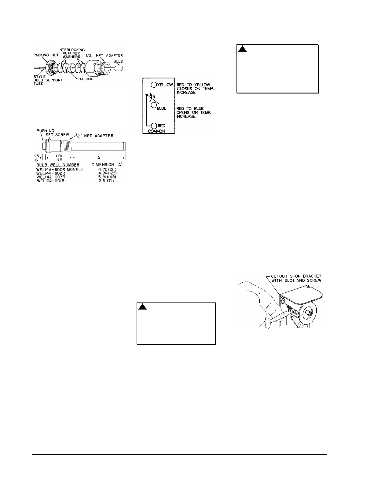
Fig. 5 -- All models have a screw
type cutout stop. The stop screw
must be loosened and moved to
the stop setting desired. Tighten
screw after setting is made.
 Loading...