Installation Instructions
Issue Date March 2016
© 2016 Johnson Controls, Inc.
Part No. 24-9890-161, Rev. C www.johnsoncontrols.com
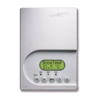
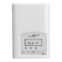
TEC2103-2 Networked Multi-Stage Thermostat
Application
The TEC2103-2 thermostat is an N2 networked
thermostat that provides control of multi-stage HVAC
equipment. The TEC2103-2 thermostat provides
exceptional accuracy through the use of a unique
Proportional-Integral (PI) time proportioning algorithm.
The algorithm virtually eliminates temperature offset
associated with traditional, differential-based on/off
thermostats. The TEC2103-2 thermostat also uses an
adaptive control logic algorithm to control the space
temperature during recovery to minimize overshoot
while providing maximum comfort.
The TEC2103-2 thermostat has Metasys® N2
communication capability. This communication allows
the user to view and adjust parameters from a remote
workstation. Additionally, the menu driven backlit
display, plain text menus, and five keys on the
TEC2103-2 thermostat make operating the thermostat
easy and intuitive.
Note: In this document, Building Automation System
(BAS) is a generic term that refers to the Metasys
Network (Network Control Module [NCM] or N30
Series), and Companion (CPN) supervisory systems.
The specific system names are used when referring to
system specific applications.
Installation
Location Considerations
Locate the TEC2103-2 thermostat:
• on a partitioning interior wall, and approximately
5 ft. (1.5 m) above the floor in a location of
average temperature
• away from direct sunlight, radiant heat, outside
walls, behind doors, air discharge grills, stairwells,
or outside doors
• away from steam or water pipes, warm air stacks,
unheated/uncooled areas, or sources of electrical
interference
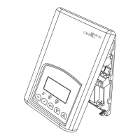
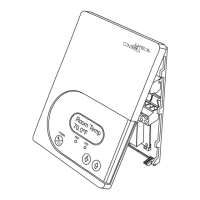
To install the thermostat:
1. Remove the security screw on the bottom of the
thermostat cover using a Phillips-head
screwdriver. Open the thermostat by pulling on
the bottom side of the thermostat cover
(Figure 1).
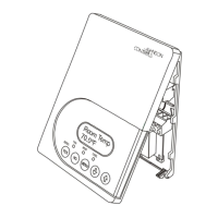
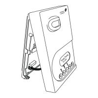
2. Unlock the Printed Circuit Board (PCB) by
carefully pressing the locking tabs to the right
(Figure 2). Open the thermostat’s PCB to the left.
3. Pull out approximately 6 in. (152 mm) of wires
from the wall and insert the cable through the
hole in the base.
4. Align the base on the wall, and using the base as
a template, mark the location of the two mounting
holes on the wall. Confirm the thermostat base is
installed with the proper side up.
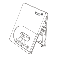
5. Use the supplied anchors and screws for
mounting on drywall or plaster. Drill two 3/16 in.
(4.7 mm) holes at the marked locations and tap
nylon anchors flush to wall surface (Figure 3).
6. Position base on the wall, insert screws through
mounting base, and fasten into wall anchors. Do
not overtighten screws.
7. Swing the thermostat PCB back to the right to
close. Gently press on the PCB to secure each of
the locking tabs.
8. Pull out the screw terminal blocks using the
pull-tabs on each connector (Figure 4).
Note: The number of terminals on the terminal
blocks varies depending on the TEC model.