EasyManua.ls Logo

Johnson Controls TEC3613-14 - User Manual

Johnson Controls TEC3613-14
40 pages
Print Icon
To Next Page IconTo Next Page
Loading...
TEC3000 Series Proportional Fan Coil
Thermostats Installation Guide
Applications
The networked TEC3000 Series Thermostat Controllers
are stand-alone and field-selectable BACnet
®
MS/TP or
N2 networked devices. Wireless networked models of the
TEC3000 Series Thermostat Controller are also available.
Proportional Fan Coil and Individual Zone Thermostat
Controllers provide control of the following:
Local hydronic reheat valves
Pressure-dependent variable air volume (VAV)
equipment with or without local reheat
Two- or four-pipe fan coils
Cabinet unit heaters
Other individual zone equipment using an on/off or
floating control input
The networked models feature a field-selectable
Building Automation System (BAS) BACnet MS/TP or N2
communication capability that enables remote monitoring
and programming for efficient space temperature control.
The wireless models (TEC30xx-xx-000) are compatible
only with the WNC1800/ZFR182x Pro Series Wireless Field
Bus System that enables communication with a building
automation system (BAS). The new wireless models
(TEC31xx-14-000) are compatible only with WRG1830/
ZFR183x Pro Series Wireless Field Bus System. All models
include a USB port configuration that reduces installation
time to allow simple backup and restore features from a
USB drive, which enables rapid cloning of configuration
between similar units.
Some models have occupancy sensing capability built into
the device. These thermostat controllers maximize up to
30% energy savings in high-energy usage commercial
buildings, such as schools and hotels, during occupied
times by using additional standby setpoints.
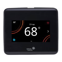
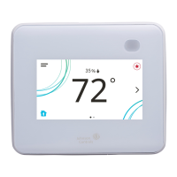
All models feature an intuitive onboard touchscreen UI
with backlit display that makes setup and operation quick
and easy. For Single-or Two-Stage Economizer Thermostat
Controller models, only the single-speed fan configuration
is supported. For TEC3x1x and TEC3x2x models, multiple
fan configurations are supported for fan coil equipment
types, as follows:
Single-speed
Multi-speed (two or three discrete speeds)
Variable-speed/EC motors (0 to 10 VDC control)
Some models support dehumidification on two-pipe
fan coil units with reheat, and four-pipe fan coil units
with or without reheat. When no heating is required,
the thermostat controller monitors space humidity and
activates dehumidification control as necessary. Heat
and/or reheat is used as required to maintain the space
temperature. For optimal dehumidification performance,
use a fan coil unit that has a multi-speed or variable-speed
fan (VSF).
Important: The TEC3000 Series Thermostat
Controller is intended to provide an input to
equipment under normal operating conditions.
Where failure or malfunction of the thermostat
controller could lead to personal injury or property
damage to the controlled equipment or other
property, additional precautions must be designed
into the control system. Incorporate and maintain
other devices, such as supervisory or alarm systems
or safety or limit controls, intended to warn of
or protect against failure or malfunction of the
thermostat controller.
Important: Le TEC3000 Series Thermostat Controller
est destiné à transmettre des données entrantes
à un équipement dans des conditions normales
de fonctionnement. Lorsqu'une défaillance ou un
dysfonctionnement du thermostat controller risque
de provoquer des blessures ou d'endommager
l'équipement contrôlé ou un autre équipement, la
conception du système de contrôle doit intégrer des
dispositifs de protection supplémentaires.Veiller
dans ce cas à intégrer de façon permanente d'autres
dispositifs, tels que des systèmes de supervision
ou d'alarme, ou des dispositifs de sécurité ou de
limitation, ayant une fonction d'avertissement
ou de protection en cas de défaillance ou de
dysfonctionnement du thermostat controller.
North American emissions
compliance
United States
This equipment has been tested and found to comply with
the limits for a Class B digital device, pursuant to Part 15
of the FCC Rules. These limits are designed to provide
reasonable protection against harmful interference in
a residential installation. This equipment generates,
uses and can radiate radio frequency energy and, if not
installed and used in accordance with the instructions,
may cause harmful interference to radio communications.
However, there is no guarantee that interference will not
occur in a particular installation. If this equipment does
cause harmful interference to radio or television reception,
which can be determined by turning the equipment
off and on, the user is encouraged to try to correct the
interference by one or more of the following measures:
Reorient or relocate the receiving antenna.
Increase the separation between the equipment and
receiver.
Connect the equipment into an outlet on a circuit
different from that to which the receiver is connected.
Consult the dealer or an experienced radio/TV
technician for help.
LIT-12013162
2020-12-15
TEC3322-1x-xxx, TEC3323-1x-xxx, TEC3622-1x-xxx,
TEC3623-1x-xxx, TEC3022-1x-xxx, TEC3023-1x-xxx,
TEC312x-14-xxx

Questions and Answers

  • K
    Kimberly WoodsSep 15, 2025
    Why Johnson Controls TEC3613-14 displays Cooling/Heating Unavailable due to Control Mode?
    • S
      Sandra ManningSep 15, 2025
      If your Johnson Controls Thermostat displays 'Idle' with a Unit Status of Cooling Unavailable due to Control Mode (despite being above cooling setpoint) or Heating Unavailable due to Control Mode (despite being below the setpoint), it could be due to the Control Mode being set incorrectly. If the Control Mode is set to Cooling Mode, but the controller requests heating, change the Control Mode to Auto or Heating. If the Control Mode is set to Heating Mode, but the controller requests cooling, change the Control Mode to Auto or Cooling.
  • K
    krogersAug 25, 2025
    How to fix 'Supply Temp Fail' on a Johnson Controls Thermostat?
    • H
      Henry DouglasAug 25, 2025
      If your Johnson Controls Thermostat is showing a 'Supply Temp Fail' error, it means the External Supply Temperature sensor is either disconnected or not working correctly. To resolve this: 1. Begin by inspecting the sensor's wiring. 2. If the disconnection was intentional, go to the menu, then Control Setup, and select Inputs to reset the sensors and clear the fault. 3. If the problem persists, you'll need to order replacement units and send the defective devices back to Johnson Controls through the RMA program.
  • J
    Joseph GrayAug 25, 2025
    What to do if Johnson Controls TEC3613-14 Thermostat displays Board Mismatch?
    • C
      Christopher LunaAug 26, 2025
      If your Johnson Controls Thermostat displays 'Board Mismatch', it means that the I/O board that the display board is currently attached to does not match the one that initially shipped with the display board. Try attaching the display board to the correct I/O board. Alternatively, a hardware failure might be causing the two boards to incorrectly identify themselves, and you should order replacement units and return the affected devices to Johnson Controls under the RMA program.
  • D
    Diane ZimmermanAug 26, 2025
    How to fix Remote Zone Temp Fail on Johnson Controls Thermostat?
    • J
      Jason PetersAug 27, 2025
      If you are experiencing a Remote Zone Temp Fail error on your Johnson Controls Thermostat, it means that the External Zone Temperature sensor has been disconnected or has failed. Here's what you can do: * Check the wiring of the sensor. * If the sensor was intentionally disconnected, reset sensors through the menu. * If the problem continues, order replacement units and return the affected devices to Johnson Controls under the RMA program.
  • C
    Courtney ParkerSep 16, 2025
    Why does Johnson Controls Thermostat provide an error when trying to upgrade firmware?
    • C
      Chase DiazSep 16, 2025
      If your Johnson Controls Thermostat provides an error when trying to upgrade firmware, it means that the firmware on the USB drive is below the minimum required version (Error code 1025). Use firmware version 3.0.2.xxxx (for networked models) or 2.0.2.xxxx (for wireless models) or higher. A reboot is required to clear the Firmware Mismatch fault that occurs.
  • C
    Charles KimSep 23, 2025
    What to do if Johnson Controls TEC3613-14 displays Firmware Mismatch?
    • A
      Angela NovakSep 23, 2025
      If your Johnson Controls Thermostat displays a Firmware Mismatch, it could be due to a previous upgrade that did not complete. In this case, upgrade the TEC3000 to the latest released version and then upgrade it to the current version again. Alternatively, the previous downgrade might not have completed because the previous version is no longer supported; in this case, reboot the TEC3000 to clear the fault.
  • R
    Rebecca BarnesSep 7, 2025
    Why is Heating Ineffective on Johnson Controls TEC3613-14 Thermostat?
    • M
      Mark LewisSep 8, 2025
      If the heating is ineffective on your Johnson Controls Thermostat, it means that the Supply Air Temperature has not increased above the configured Supply Air Temperature Alarm Offset while heating has been active for at least the Supply Air Temperature Alarm Delay. To resolve this, verify that the heating elements on the rooftop are functioning correctly.
  • P
    Philip Young Jr.Sep 8, 2025
    Why is Cooling Ineffective on Johnson Controls TEC3613-14 Thermostat?
    • G
      Gabriella SmithSep 9, 2025
      If cooling is ineffective on your Johnson Controls Thermostat, it means the Supply Air Temperature has not decreased below the configured Supply Air Temperature Alarm Offset while cooling has been active for at least the Supply Air Temperature Alarm Delay. Verify that the cooling elements on the rooftop are functioning correctly.
  • J
    Jimmy JonesSep 2, 2025
    Why Johnson Controls Thermostat shows Humidity Unreliable?
    • N
      Norman GarzaSep 2, 2025
      If your Johnson Controls Thermostat displays 'Humidity Unreliable', it means the zone humidity reading was reliable but has now failed. If the source of zone humidity was the onboard sensor, contact Johnson Controls product sales and support. If the source of zone humidity was a BAS, check the BAS to ensure it is still online and providing the TEC with the humidity reading. If removal of the BAS mapping was intentional, reset sensors through the menu.
  • M
    Michele RodriguezAug 31, 2025
    What does Changeover Fail mean on Johnson Controls TEC3613-14 Thermostat?
    • S
      smithsarahAug 31, 2025
      If you see a 'Changeover Fail' message on your Johnson Controls Thermostat, it means the Supply Temperature Sensor is not installed, has failed, or has been disconnected, and the TEC can no longer detect changeover mode to cool or heat. Follow the same steps as for a Supply Temp Fail alarm to resolve this issue.

Summary

Important Safety and Operational Guidance

North American Emissions Compliance

Installation Overview

Wiring Procedures

Wiring Safety and Best Practices

Emphasizes crucial safety warnings and regulatory compliance for electrical connections.

Terminal Identification

Wiring Diagrams

Setup and Adjustments Overview

Touchscreen Icons Reference

USB Port Operations

Loading Firmware

Step-by-step guide to update the thermostat's firmware via USB.

Backing Up and Restoring Settings

Instructions for saving and retrieving thermostat configurations using a USB drive.

Network Configuration

Fan Coil Supply Fan Configuration

Control and Fan Mode Settings

Changeover Configuration

Dehumidification Control Setup

Temperature Setpoint Configuration

Occupancy Configuration

Local Schedule Setup

Motion Sensor Configuration

PID;PRAC+ Control Tuning

Configurable Binary Inputs

Auxiliary Output Configuration

Commissioning Mode and Scheduled Circulation

Configurable Analog Inputs (AIs)

Networked Sensors

Sensor Data Priorities and Diagnostics

Available Fault Diagnostics

Lists and describes potential faults, including fan status, runtime, temperature alarms, and trends.

Troubleshooting Faults

Troubleshooting Details

Technical Specifications

Johnson Controls TEC3613-14 Specifications

General IconGeneral
ModelTEC3613-14
DisplayLCD
Power Supply24V AC
MountingWall Mount
ProgrammableYes
Backup BatteryNo
TypeDigital
ControlCooling and Heating
Stages1
CompatibilityHeat Pump

Related product manuals