System 450™ Series Control Modules with Relay Outputs Installation Instructions 13
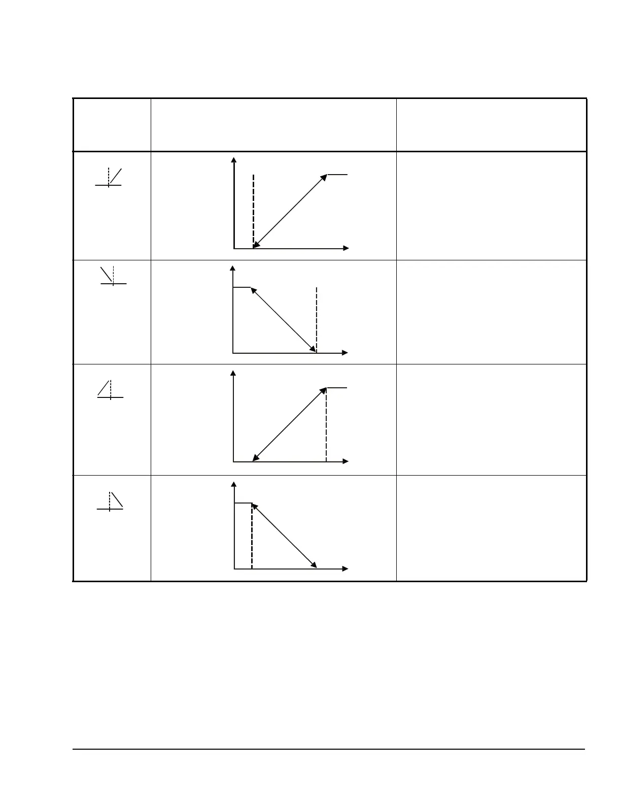
Table 7 shows the four Control Ramp icons and the
associated analog output setup value relationships.
Table 8 provides information, procedures, guidelines,
and screen examples for setting up analog outputs that
reference standard or High Input-Signal Selection
sensors. See Figure 7 on page 21 for example menu
flow of the Analog Output 3 set up in Table 8.
Table 7: Analog Output Control Ramp Icons
Control Ramp
Displayed on
LCD
Control Action Set the Analog Output Value
Relationships for the Desired Control
Action and Corresponding Control
Ramp
SP < EP
OSP < OEP
SP > EP
OSP < OEP
SP > EP
OSP > OEP
SP < EP
OSP > OEP
Output Minimum at SP
a
l
SP=50°F EP=60°
Output Minimum at SP
EP=50°F SP=60°F
Output Maximum at SP
EP=50°F SP=60°F
P
r
o
p
o
r
t
i
o
n
a
l
B
a
n
d
Output Maximum at SP
SP=50°F EP=60°F
OSP=100%
OEP=0%
P
r
o
p
o
r
t
i
o
n
a
l
B
a
n
d
 Loading...