System 450™ Series Control Modules with Relay Outputs Installation Instructions16
Differential Control
Beginning with Version 2.00 firmware, standard System
450 control modules include Differential Control
capability. Differential control is used to monitor and/or
maintain a given difference in a condition (temperature,
pressure, or humidity) between two sensor points
within a system, process, or space.
The Differential Control feature enables a System 450
control system to monitor the temperature, pressure, or
humidity differential between two sensors of the same
type (Sn-1 and Sn-2) and control relay and/or analog
outputs based on the sensed differential value relative
to user-selected differential values (dON, dOFF, dSP,
and dEP).
When a Differential Control sensor (Sn-d) is set up, the
displayed differential sensor value is a calculated
variable value; (Sn-d) = (Sn-1) – (Sn-2).
Note: The System 450 Differential Control sensor
(Sn-d) value is always equal to Sn-1 minus Sn-2.
Therefore, depending on the intended control action of
the output, the differential value may be either a
positive or negative value.
The Sn-d value is displayed in the System Status
screens as either a temperature differential value
(dIFT), pressure differential value (dIFP), or humidity
differential value (dIFH). The unit of measurement
associated with the displayed differential value is
determined by the Sn-1 and Sn-2 Sensor Type. See
Table 3 on page 7 for Sensor Types and their units of
measurement.
The relay output setup values dON and dOFF are also
condition differential values.
• When a relay output is set up for differential
control, System 450 controls the relay state (On or
Off) based on the difference between Sn-1 and
Sn-2 (Sn-d) relative to the user-selected differential
On (dON) and differential Off (dOFF) values.
• When an analog output is set up for differential
control, System 450 controls the analog signal
strength (0 to 100%) based on the difference
between Sn-1 and Sn-2 (Sn-d) relative to the user-
selected differential setpoint (dSP) and differential
endpoint (dEP) values.
Differential Sensor Failure Mode
Any output set up to reference the Differential Sensor
(Sn-d) enters the selected Sensor Failure mode when
either Sn-1 sensor, Sn-2 sensor, or the sensor wiring
fails.
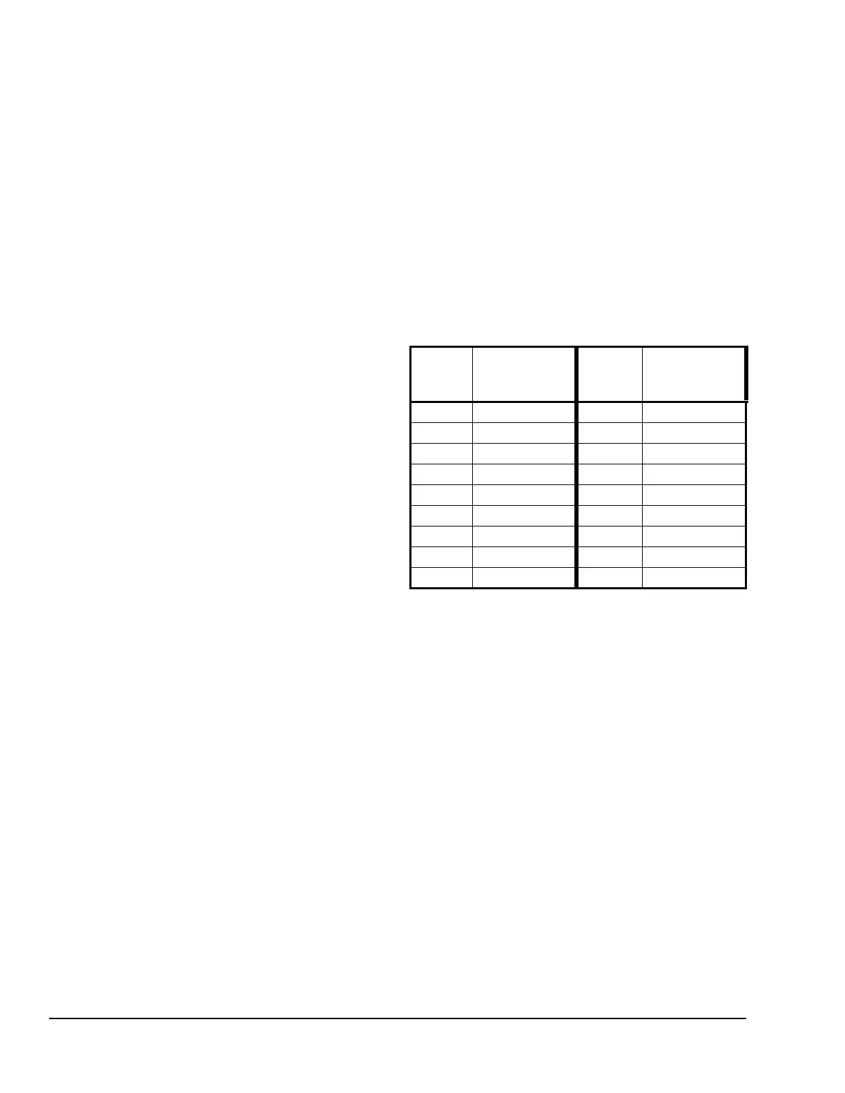
Differential Sensor Range of Usable Values
Because of the way that the System 450 Differential
Sensor (Sn-d) is set up and calculated with two
identical sensors (Sn-1 and Sn-2), the Range of Usable
Values is twice as large as a single sensor. Each
Sensor Type has an equal number of positive and
negative values. See Table 9 for the Range of Usable
Values when an output references Sn-d.
Setting Up an Output for Differential Control
Table 10 provides information, procedures, guidelines,
and screen examples for setting up relay outputs that
reference the Differential Control sensor.
Table 11 provides information, procedures, guidelines,
and screen examples for setting up analog outputs that
reference the Differential Control sensor.
Figure 8 on page 22 shows the menu flow used to set
up the output examples in Table 10 and Table 11.
Table 9: Ranges of Usable Values for Sensor
Types in Differential Control Applications
Sensor
Type
Sn-d Range
of Usable
Values
Sensor
Type
Sn-d Range
of Usable
Values
°F -290 to 290 P 30 -30.0 to 30.0
°C -161.0 to 161.0 P 50 -50.0 to 50.0
rH -95 to 95 P100 -100.0 to 100.0
P 0.5 -0.500 to 0.500 P110 -110.0 to 110.0
P 2.5 -2.50 to 2.50 P200 -200 to 200
P 5 -5.00 to 5.00 P500 -500 to 500
P 8 -9.00 to 9.00 P750 -750 to 750
P 10 -10.00 to 10.00 HI°F -380 to 380
P 15 -16.0 to 16.0 HI°C -210.0 to 210.0
 Loading...