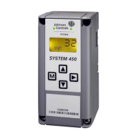
System 450™ Series Control Modules with Relay Outputs Installation Instructions18
Sensor Failure Mode Selection Screen: Select the differential output’s mode of operation if either of the
referenced sensors (Sn-1 or Sn-2) or the sensor wiring fails. The output operates in the selected mode
until the failure is remedied. Sensor Failure mode selections for Relay Outputs include:
• ON = Output relay remains On during sensor failure.
• OFF = Output relay remains Off during sensor failure.
7. Press or to select this output’s mode of operation if a referenced sensor or sensor wiring
fail. Press to save your sensor failure mode selection and go to the Edit Sensor Screen.
The screen example shows OFF selected as the Sensor Failure mode for Output 1.
Edit Sensor Screen: This screen displays the Differential Sensor (Sn-d) that this output currently
references. Typically, no action is taken in this screen. But if you need to change the sensor that this
output references, you can select a different sensor for this output in this screen.
Note: If you change the Sn-d sensor to a different sensor, the output is no longer a Differential Control
output and you must set the output up again for the new sensor selection.
8. If you do not need to change this output’s sensor, simply press to save the current sensor
selection and return to the Relay Output Setup Start screen.
To change the sensor this output references, press or to select the new sensor that this
output references. Then press to save the new sensor selection and return to the Relay ON
Selection screen (ON or dON). If the new sensor has a different Sensor Type from the
previously referenced sensor, repeat the output setup procedure for this output.
This Relay Output is now set up in the System 450 UI.
The screen example shows Sn-d as the selected Sensor for Output 1.
Relay Output Setup Start Screen: After you have set up this Relay Output, you can go to another
Output Setup Start screen, the Sensor Setup Start screen, or return to the Main screens.
9. Press to scroll through the remaining Output Setup Start screens and return to the Sensor
Setup Start screen, or press and simultaneously to return to the System 450 Main
screens.
The screen example shows the Relay Output Setup Start screen for Output 1.
Table 11: System 450 Setup Screen Information and Procedures for Analog Outputs with Differential
Control (Part 1 of 3)
LCD Screen Name, Description/Function, User Action, Example
Analog Output Setup Start Screen: The output numbers and the output type (relay or analog) are
determined by the module types and configuration of your control system’s module assembly and are
automatically assigned when you connect power to the module assembly. (See Setting Up a Control
System in the User Interface on page 5.)
Note: You must set up the system’s sensors before you can set up the system outputs, and you must set
up the Differential Control sensor (Sn-d) before you can set up an output with Differential Control. (See
Setting Up System 450 Sensors
for information on setting up the Differential Control sensor.)
1. Press
to go to this output’s Sensor Selection screen.
The screen example shows the Analog Output Setup Start screen for Output 2.
Sensor Selection Screen: Selecting the Differential Control sensor (Sn-d) here establishes this output as
a Differential Control output. Differential Control outputs have several different setup parameters and
value ranges from standard and High Input-Signal Selection outputs.
Note: To set up an output for Differential Control, the Differential Control sensor (Sn-d) must be already
set up in the System 450 UI (See Setting Up System 450 Sensors
for more information.), and you must
select Sn-d in the Sensor Selection screen. If Sn-d is not selected here, the Differential Control setup
screens do not appear. If a sensor is already selected for this output, the Sensor Selection screen does
not appear here, instead the Setpoint Selection screen (SP or dSP) appears instead.
2. Press or to select the Differential Control sensor (Sn-d) as the sensor this output
references. Press
to save your sensor selection and go to the Setpoint Selection screen.
The screen example shows Sn-d as the selected Sensor for Output 2.
Table 10: System 450 Setup Screen Information and Procedures for Relay Outputs with Differential Control
(Part 2 of 2)
LCD Screen Name, Description/Function, Procedures, and Example
Sn-d
M
 Loading...