System 450™ Series Control Modules with Relay Outputs Installation Instructions 19
Differential Setpoint Selection Screen: Differential Setpoint (dSP) is the target value that the controlled
system drives towards and along with Differential End Point (dEP), defines this output’s proportional band.
The dSP value is a differential value that represents a (selected) difference in the condition (temperature,
pressure, or humidity) between Sn-1 and Sn-2 (Sn-1 minus Sn-2). Depending on the intended
proportional control action and the physical location of Sn-1 and Sn-2 sensors in the condition process,
dSP may be a positive or negative value.
Note: The unit of measurement, resolution increment, minimum proportional band, and range of usable
values for dSP and dEP are determined by the Sensor Type selected for Sn-1 and Sn-2. (See Table 3 and
Table 9 for more information.) The output’s minimum proportional band (between dSP and dEP) is
automatically enforced in the output’s Setpoint and End Point Selection screens.
3. Press or to select this output’s Differential Setpoint value. Press
to save your
Differential Setpoint value selection and go to the End Point Selection screen.
The screen example shows a dSP value of 25 (psi) selected for Output 2.
Differential End Point Selection Screen: Differential End Point (dEP) is the target value that the
controlled system drives towards and along with Differential Setpoint (dSP), defines this output’s
proportional band. The dEP value is a differential value that represents a (selected) difference in the
condition (temperature, pressure, or humidity) between Sn-1 and Sn-2 (Sn-1 minus Sn-2). Depending on
the intended proportional control action and the physical location of Sn-1 and Sn-2 sensors in the
condition process, dEP may be a positive or negative value.
Note: The unit of measurement, resolution increment, minimum proportional band, and range of usable
values for dSP and dEP are determined by the Sensor Type selected for Sn-1 and Sn-2. (See Table 3 and
Table 9 for more information.) The output’s minimum proportional band (between dSP and dEP) is
automatically enforced in the output’s Setpoint and End Point Selection screens.
4. Press or to select this output’s Differential End Point value. Press
to save your
Differential End Point value selection and go to the %Output Signal Strength at Setpoint
Selection screen.
The screen example shows a dEP value of 30 (psi) selected for Output 2.
Output Signal Strength at Setpoint Selection Screen: Select the strength of the signal that this output
generates when the sensed condition is at the Differential Setpoint (dSP) value. The signal strength range
is 0 to 100 (%).
5. Press or to select this output’s %Output Signal Strength at Setpoint value. Press
to
save your selection and go to the %Output Signal Strength at End Point Selection screen.
The screen example shows an OSP value of 10 (%) selected for Output 2. Therefore Output 3 generates
10% of the total signal strength (1 V or 5.6 mA) when the input is at the Setpoint value of 200 (psi).
Output Signal Strength at End Point Selection Screen: Select the strength of the signal that this output
generates when the sensed condition is at the Differential End Point (dEP) value. The signal strength
range is 0 to 100 (%).
6. Press or to select this output’s %Output Signal Strength at End Point value. Press
to
save your selection and go to the Integration Constant Selection screen.
The screen example shows an OEP value of 90 (%) selected for Output 2. Therefore Output 3 generates
90% of the total signal strength (9 V or 18.4 mA) when the input is at the End Point value of 250 (psi).
Integration Constant Selection Screen: An integration constant allows you to set up proportional plus
integral control for this analog output. proportional plus integral control can drive the load closer to
Setpoint than proportional only control.
Note: Initially, you should select the I-C value of 0 (zero) for no integration constant. Refer to the System
450 Series Technical Bulletin (LIT-12011459) for more information on proportional plus integral control
and setting an integration constant in the System 450 UI.
7. Press or to select this output’s Integration Constant for proportional plus integral control.
Press
to save your selection and go to the Sensor Failure Mode Selection screen.
The screen example shows an I-C value of 0 (zero) selected for Output 2.
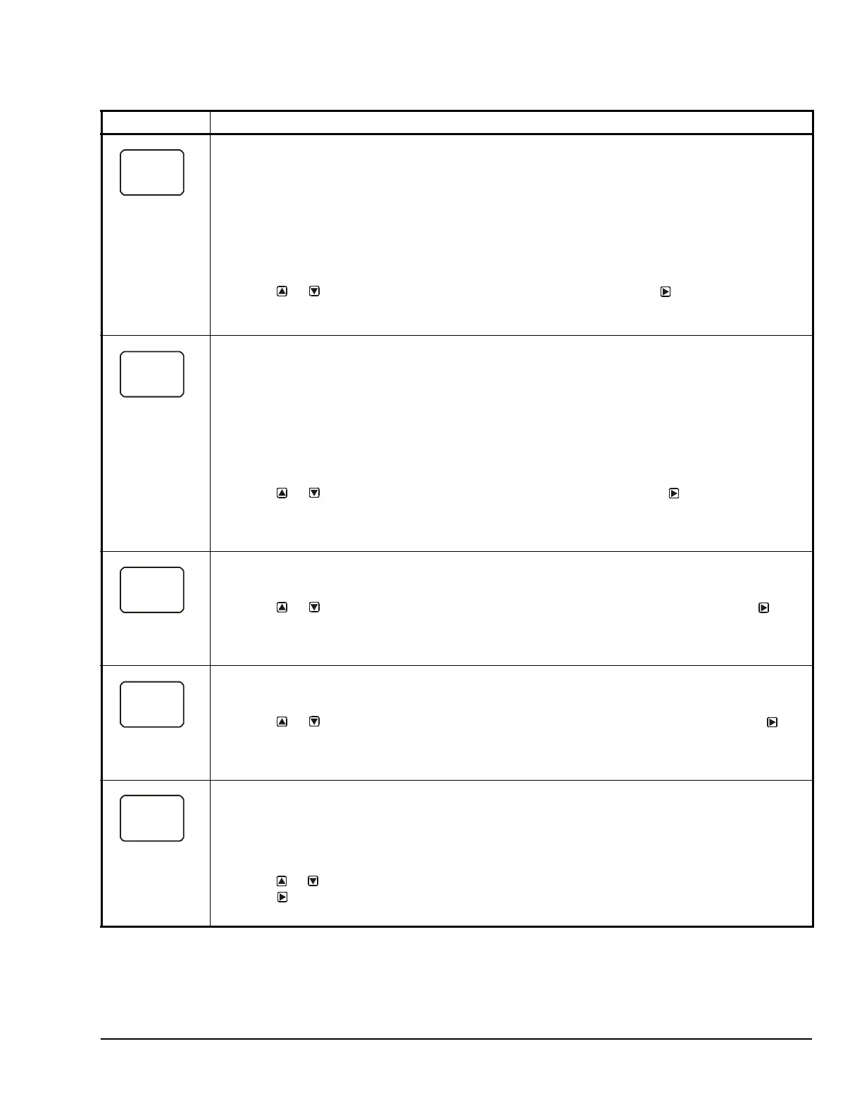
Table 11: System 450 Setup Screen Information and Procedures for Analog Outputs with Differential
Control (Part 2 of 3)
LCD Screen Name, Description/Function, User Action, Example
dSP
30.0
dEP
25.0
 Loading...