System 450™ Series Control Modules with Relay Outputs Installation Instructions4
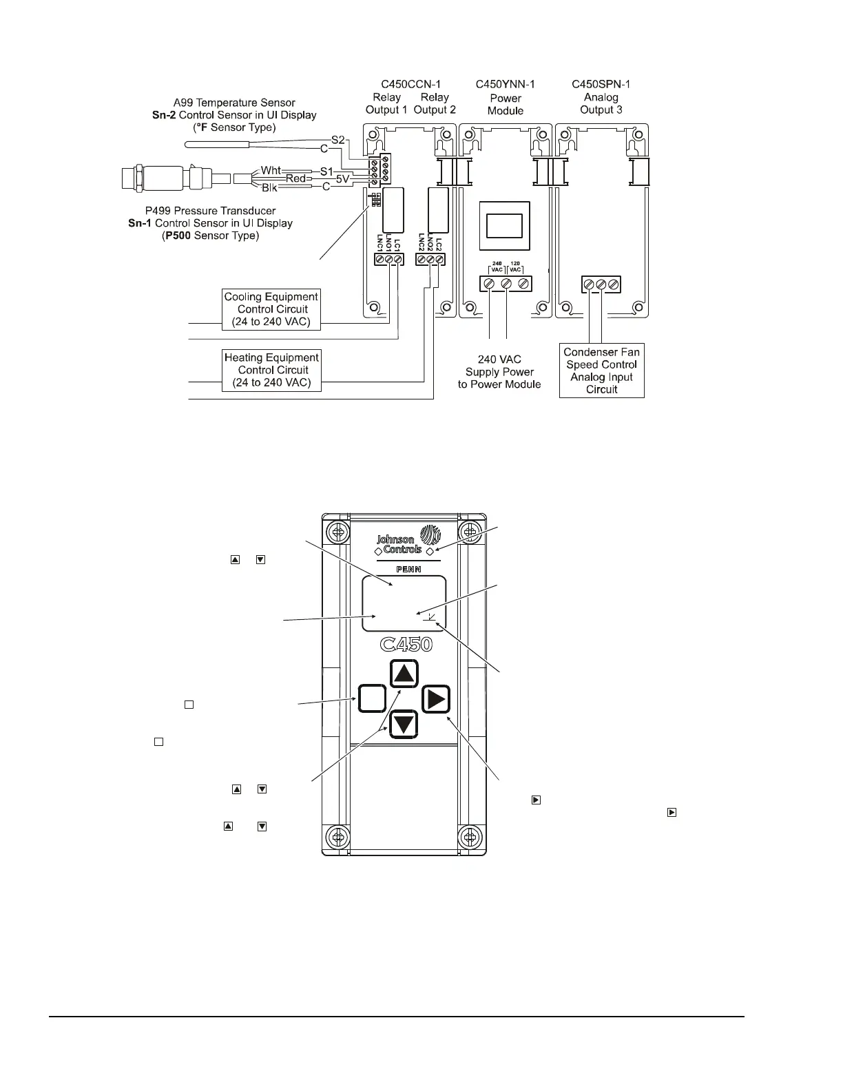
Figure 3: Example System 450 Heat/Cool System with Condenser Fan Speed Control
FIG:sys450_app_exmpl
0-10 VDC or
Analog Output
AO2
COM
AO1
Note:
In 120 VAC applications, L1 must be the Hot lead
and L2 must be the Neutral/Common lead.
Sn-1
Sn-2
Sn-3
Active/Passive Sensor Jumpers
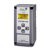
Figure 4: System 450 Control Module Output Relay LEDs,
LCD, Four-Button Touch Pad User Interface
Displays a numerical
value that identifies the output associated
with the status or setup value shown
on the screen. Output numbers are
automatically determined by the outputs'
physical positions (left to right) in the
module assembly. (Here, 4 = Output 4.)
Control Ramp Icon:
Displays whether an
analog output (only) is set as direct-acting
or reverse acting, and whether the output
signal strength is at minimum or maximum
when the sensed property is at Setpoint.
The control ramp icon displayed is
determined by the output's SP, EP, OSP,
and OEP setup values.
Menu Button:
Press to move through the
sensor and output setup start screens.
When moving through the status or setup
screens, press to return to the status start
screen or set up start screen.
M
M
Status or Setup Identifier:
or
OSP
Displays the
unit of measurement, output, sensor number,
setup parameter for the displayed status or
setup value. (Here, the setup identifier
represents % output signal strength at setpoint.)
Up and Down Buttons:
Press or to select
a different value for any flashing value in the
setup value field. In the Main (sensor status)
screens, press and hold both and for
5 seconds to access the Setup Start screens.
Status or Setup Value:
or
Displays the current
input status, output status setup parameter
value for the displayed input sensor, output
and/or setup parameter. select
a different parameter value when the value
is flashing. (Here, 100 = 100%.)
Press or to
M
Light-Emitting Diode (LED):
on Relay Control Module and Relay
Expansion Modules (only) indicates if the
associated relay output is on or off.
FIG:sys450cntrl_modul
Next Button:
press to scroll through the system status
screens. In a setup screen, press to save
the (flashing) setup value and go to the
next setup screen.
00
 Loading...