System 450™ Series Control Modules with Relay Outputs Installation Instructions 3
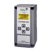
Table 1: System 450 Terminal Wiring Information
Label Terminal Function Wire Sizes
24V Accepts 24 VAC supply power, when a C450YNN power module is not connected,
and provides power terminal for 24 VAC (humidity) sensors.
0.08 mm
2
to 1.5 mm
2
28 AWG to 16 AWG
5V Provides 5 VDC power for active sensors.
Sn-1, Sn-2,
Sn-3
Accepts passive or active (0–5 VDC) input signals from sensors.
Note: You must position the Active/Passive Sensor Jumper (Figure 3 and
Figure 6) correctly for each sensor in your control system before operating the
system. See Setting Active/Passive Sensor Jumpers for more information.
C
(Three
Terminals)
Provide low-voltage Common connections for 24 VAC power and passive or active
sensors connected to the 5V, Sn1, Sn2, and Sn3 terminals.
Note: The three C terminals are connected internally and can be connected to
ground in the field.
LNC1, LNC2 Connects control circuit to the Normally Closed (N.C.) contact on the SPDT relay.
0.08 mm
2
to 2.5 mm
2
28 AWG to 14 AWG
LNO1, LNO2 Connects control circuit to the Normally Open (N.O.) contact on the SPDT relay.
LC1, LC2
Connects line (power) to Common (C) on the SPDT
1
relay.
1. See Internal SPDT Relay insert in Figure 2 for more System 450 relay contact and terminal information. See Technical
Specifications for SPDT relay electrical ratings.
Figure 2: C450CxN-2 Wiring Terminals
Sn2
Sn3
24V
Sn1
Common (C) terminals
are connected
internally.
Internal
SPDT Relay
Normally Closed/Off
Position
LNC1
LNO1
LC1
Supply Power and
Control Sensor Terminals
Low Voltage (<30 V)
Dry-Contact, Line-Voltage
Relay Output Terminals
(See
for Electrical Ratings.)
Technical Specifications
6-Pin
Module
Connector
a second output relay
and terminal block labeled
LNC2, LNO2, and LC2.
FIG:sys450_rly_cntrl_wir
Note:
The relay output terminals connect to an internal SPDT
relay and do supply any power to the application.
 Loading...