System 450™ Series Control Modules with Relay Outputs Installation Instructions8
Table 4 provides sensor setup information, procedures,
and example screens. Figure 7 on page 21 provides a
System 450 UI setup example.
4. Many of the 1,000 ohm Nickel temperature sensors that can be set up as HI°F or HI°C Sensor Types are not designed for
use across the entire Range of Usable Values for HI°F and HI°C Sensor Types. Refer to the Technical Specifications
sections in the TE-6000 Series Temperature Sensing Elements Product Bulletin (LIT-216288), the TE-6300 Series
Temperature Sensors Product Bulletin (LIT-216320), and the TE-6800 Series Temperature Sensor Product Bulletin
(LIT-12011542) to determine the temperature range that the various 1,000 ohm Nickel temperature sensors are specified to
operate in.
Table 4: System 450 Sensor Setup Screen Information and Procedures (Part 1 of 2)
LCD Screen Name, Description/Function, User Action, and Example
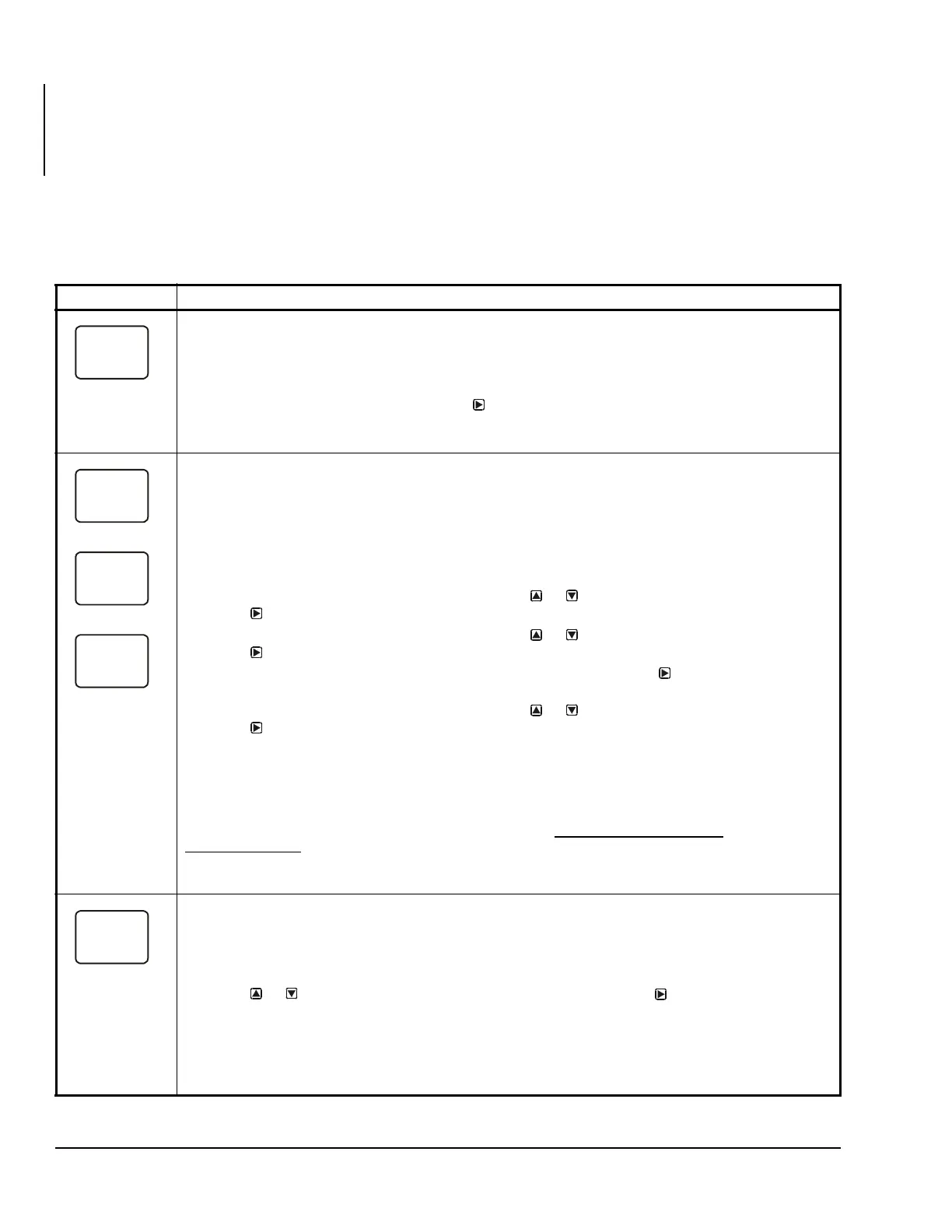
Sensor Setup Start Screen: The Sensor Setup Start screen is the first screen displayed when you
access the System 450 setup screens. From the Sensor Setup Start screen you can navigate to the
Output Setup Start screens or the Sensor Setup screens. See Figure 7.
Note: You must set up the input sensors before you can set up the control system outputs. The Sensor
Setup Start screen is view-only; selections are not made in Setup Start screens.
1. In the Sensor Setup Start screen, press
to go to the first Sensor Type Selection screen
(Sn-1) and begin setting up the sensors in your control system.
The screen example shows the Sensors Setup Start screen with flashing dashes.
Sensor Type Selection Screens: The Sensor Type you select for an input sensor automatically
determines the setup parameters and values for each output that is set up to reference that sensor. See
Table 3 for information about System 450 sensors/transducers, Sensor Types, condition type, units of
measurement, minimum control band or proportional band, setup values, value ranges, and product code
numbers.
Note: For outputs to operate properly, the selected Sensor Type must match the sensor/transducer
model wired to the control module, and the sensor/transducer must be wired to the proper control module
input terminals.
2. In the Sn-1 Sensor Type Selection screen, press or to select the desired Sensor Type.
Press
to save your selection and go to the Sn-2 Sensor Type Selection screen.
3. In the Sn-2 Sensor Type Selection screen, press or to select the desired Sensor Type.
Press to save your selection and go to the Sn-3 Sensor Type Selection screen.
Note: If your control system does not use three input sensors, simply press
while the two dashes are
flashing in a Sensor Type Selection screen to save no Sensor Type and go to the next setup screen.
4. In the Sn-3 Sensor Type Selection screen, press or to select the desired Sensor Type.
Press
to save your selection and either:
• go to the Temperature Offset Setup screen for the first temperature sensor in your system.
• return to the Sensor Setup Start Screen, if your control system has no temperature sensors.
Note: Beginning with firmware Version 2.00, if you select the same Sensor Type for Sn-1 and Sn-2, two
additional functional sensors (Sn-d and HI-2) are available for selection when you set up the control
system outputs. If you select the same Sensor Type for Sn-1, Sn-2 and Sn-3, then functional sensor HI-3
is also available for selection when you set up outputs. See High Input-Signal Selection
on page 9 and
Differential Control
on page 16 for more information.
The screen examples show Sn-1 with the P500 Sensor Type selected; Sn-2 with the °F Sensor Type
selected; and Sn-3 with the no Sensor Type selected.
Temperature Offset Selection Screens: Select a temperature offset for the temperature inputs (only) in
your control system.
Sensor Type °F enables an offset of +/- 5°F in 1 degree increments.
Sensor Type °C enables an offset of +/- 2.5°C in 0.5 degree increments.
Note: The temperature offset changes the displayed temperature value by the selected offset value.
5. Press or to select the desired temperature offset value. Press :
• to go to the next Temperature Offset Selection screen (if there are additional temperature
sensors in your control system) and repeat this step for each temperature sensor.
• to return to the Sensor Setup Start screen.
The screen example shows an OFFS value of -3 (°F) for Sensor 2. Therefore a sensed temperature value
of 75 (°F) at Sensor 2 is displayed as 72 (°F).
2
 Loading...