System 450™ Series Control Modules with Relay Outputs Installation Instructions 15
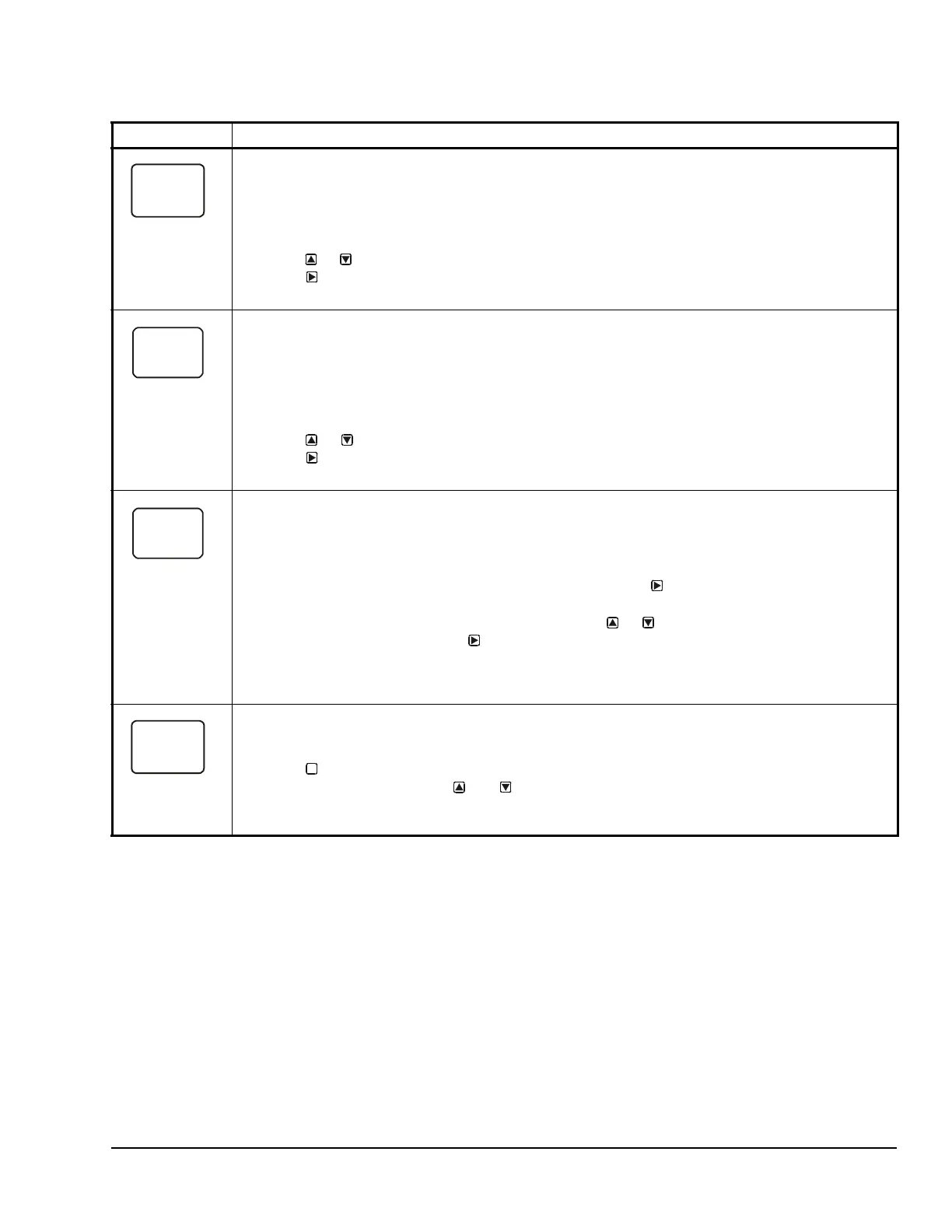
Integration Constant Selection Screen: An integration constant allows you to set up proportional plus
integral control for this analog output. proportional plus integral control can drive the load closer to
Setpoint than proportional only control.
Note: Initially, you should select the I-C value of 0 (zero) for no integration constant. Refer to the System
450 Series Technical Bulletin (LIT-12011459) for more information on proportional plus integral control
and setting an integration constant in the System 450 UI.
7. Press or to select this output’s Integration Constant for proportional plus integral control.
Press
to save your selection and go to the Sensor Failure Mode Selection screen.
The screen example shows an I-C value of 0 (zero) selected for Output 3.
Sensor Failure Mode Selection Screen: Select the output’s mode of operation if a referenced sensor or
sensor wiring fails. If the output references functional sensors HI-2 or HI-3, the output enters the Sensor
Failure mode whenever one of the referenced sensors or sensor wiring fails. The output operates in the
selected Sensor Failure mode until the failure is remedied. Sensor Failure mode selections for Analog
Outputs include:
• ON = Output generates the selected OEP signal strength during sensor failure.
• OFF = Output generates the selected OSP signal strength during sensor failure.
8. Press or to select this output’s mode of operation if the sensor or sensor wiring fails.
Press to save your selection and go to the Edit Sensor Selection screen.
The screen example shows OFF selected as the Sensor Failure mode for Output 3.
Edit Sensor Selection Screen: This screen displays the sensor that this output currently references.
Typically, no action is taken in this screen. But if you need to change the sensor that this output
references, you can select a different sensor for this output in this screen.
Note: If you change the sensor that an output references to a sensor with a different Sensor Type, the
default setup values for the output change, and you must set the output up again.
9. If you are not changing this output’s sensor, simply press to save the current sensor
selection and return to the Analog Output Setup Start screen.
To change the sensor this output references, press or to select the new sensor that this
output references. Then press to save the new sensor selection and return to the Setpoint
Selection screen (SP or dSP). If the new sensor has a different Sensor Type from the previously
referenced sensor, repeat the output setup procedure for this output.
The screen example shows Sn-2 as the selected Sensor for Output 3.
Analog Output Setup Start Screen
After you have set up this Analog Output, you can go to another Output Setup Start screen, the Sensor
Setup Start screen, or return to the Main screens.
10. Press to scroll through the remaining Output Setup Start screens and return to the Sensor
Setup Start screen, or press and simultaneously to return to the System 450 Main
screens.
The screen example shows the Analog Output Setup Start screen for Output 3.
Table 8: System 450 Setup Screen Information and Procedures for Analog Output with Standard and High
Input-Signal Selection Control (Part 2 of 2)
LCD Screen Name, Description/Function, User Action, Example
M