System 450™ Series Control Module with Ethernet Communications Installation Instructions
47
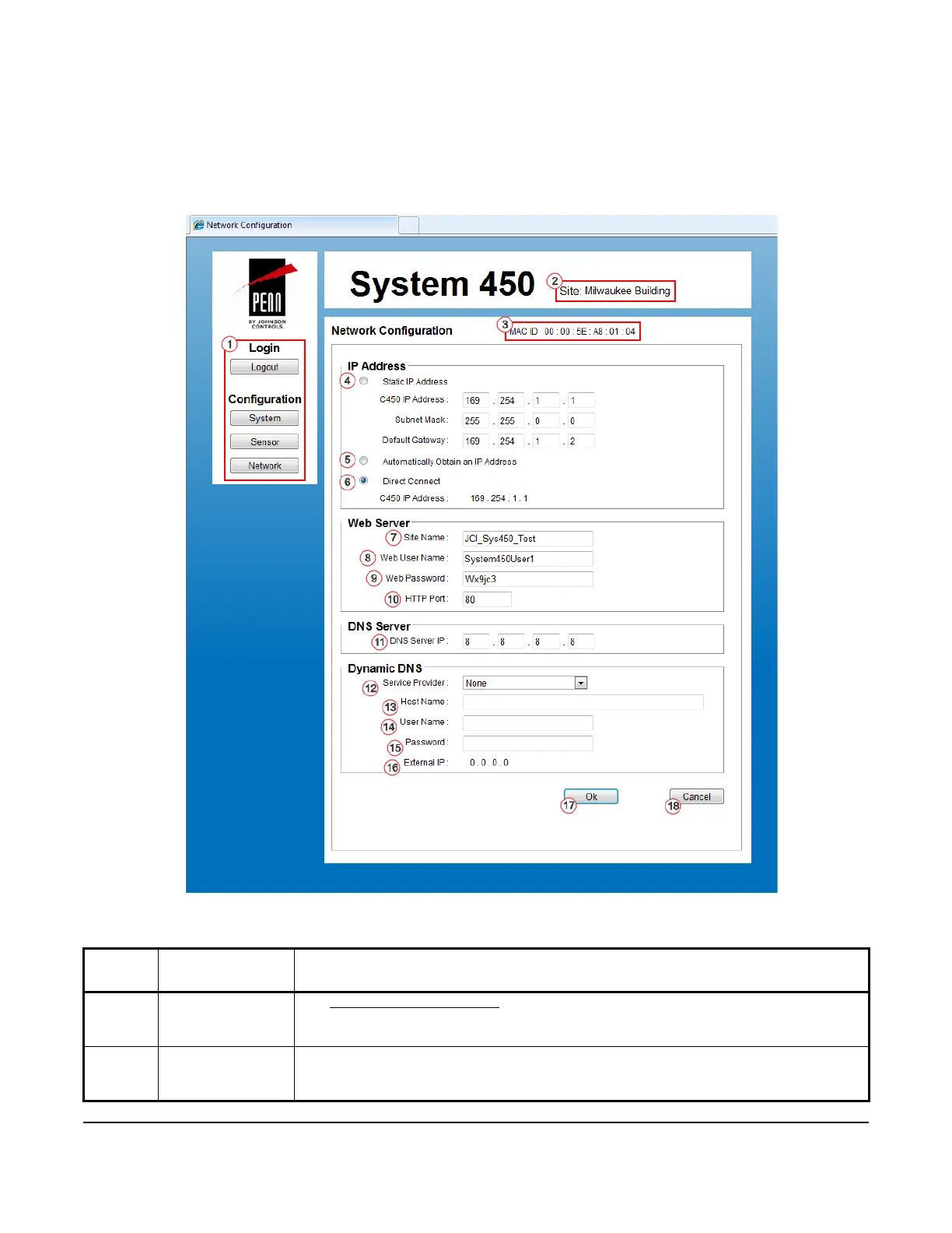
Network Configuration Page
Figure 13 shows an example Network Configuration Page for a System 450 control system that is set up and
operating.
Table 19 provides descriptions, user actions, and references for the items called out in Figure 13.
Table 19: System 450 Web UI Relay Output Configuration Page, User Actions, Descriptions, and
References (Part 1 of 3)
Callout
Number
Identifier / Item
Name
User Actions, Descriptions, References
1 Logout and
Configuration
Buttons
See System Configuration Page on page 35 for descriptions and user actions regarding the
Logout, System, Sensor, and Network buttons.
2Site NameDisplays the assigned site name. You can assign a website name on the Network
Configuration page.
See Site Name below for more information about assigning the site name.
Figure 13: System 450 Network Configuration Page Example
 Loading...