898150-UIM-B-0113
28 Johnson Controls Unitary Products
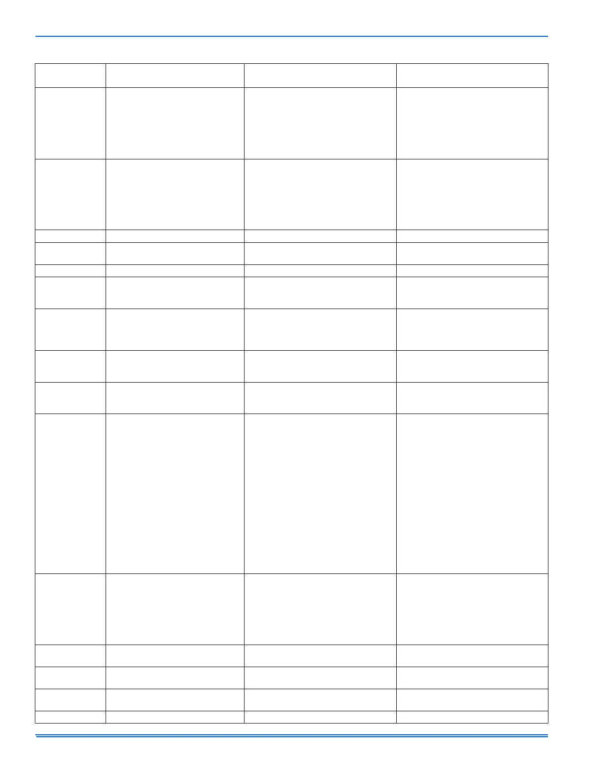
H6 Indoor fan not communicating All system functions are terminated.
Possible Indoor control failure or indoor
motor failure.
• Check wiring between fan motor and in-
door control.
• Check wiring between fan motor and ter-
minal marked OFFAN.
• Replace one or both, if necessary.
H7 Compressor lost-step protection
If this condition is detected six times within
one hour, system will shut down.
The following conditions will generate this
error:
• Unable to detect rotor position during
operation
• Actual rotor rotations exceed set speed.
Outdoor unit must be de-energized and re-
energized to resume normal operation.
Lc Unit start-up failure All system functions are terminated. See unit start-up troubleshooting charts.
Ld Compressor loss of phase protection
Outdoor unit must be de-energized and re-
energized to resume normal operation.
Compressor start up phase current is
lower than 0.5 amps.
LE Compressor locked rotary protection Compressor unable to start. De-energize system and restart.
LP Indoor and outdoor unit mismatch All system functions are terminated.
The two system components are mis-
matched. Refer to engineering handbook
for correct match-up.
L3 Outdoor DC fan motor malfunction All system functions are terminated.
• Check wiring between fan motor and out-
door control terminal marked OFFAN.
• If wiring is correct, replace outdoor DC
fan motor.
L9 Power factor protection All system functions are terminated.
Indoor unit is experiencing either a high or
low input voltage condition. Verify proper
input voltage at terminal strip N(1) and 3.
Pc
Current detect circuit malfunction
or current sensor malfunction
Outdoor unit must be de-energized and re-
energized to resume normal operation.
The offset voltage is higher than the limit
value. If this condition is detected six times
with in one hour, system will shut down.
PH High voltage protection
• Check input voltage on outdoor unit ter-
minal strip (N and L terminals).
• If voltage is higher than 265VAC, discon-
nect power to unit. Correct input voltage
problem before reapplying power to sys-
tem.
• If voltage is below 265VAC, then check
capacitor while unit is turned off.
• If voltage is between 200-208V, capacitor
is working properly
• If voltage is some other value, replace
capacitor.
• If voltage is some other value, replace
capacitor.
• If input voltage and capacitor are normal,
replace outdoor control.
PL Low voltage protection All system functions are terminated.
• Check input voltage on outdoor unit ter-
minal strip (N and L terminals).
• If voltage is lower than 150VAC, restart
system and check power again.
• 9 - 12 kBtu, 208-230VAC systems only --
Check reactor (choke) line connection on
outdoor control terminal marked AC-L2.
PU Capacitor charge failure All system functions are terminated.
Refer to the ProficienTECH Ductless Splits
Technical Training Manual.
P5 Compressor overcurrent protection All system functions are terminated.
Refer to the ProficienTECH Ductless Splits
Technical Training Manual.
P6
Communication failure between
main board and driver board
All system functions are terminated except
indoor fan.
Communication bus will automatically
reset and resume normal operation.
P7 Outdoor control failure All system functions are terminated. Replace outdoor control.
TABLE 12:
Error Codes
Indoor Character Display System Status
Troubleshooting for
Possible Causes
 Loading...


