E-Link Gateway Installation Instructions 11
Wiring
Install the wiring so it does not cause a hazard, and is
protected against electrical and mechanical damage.
Power
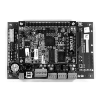
The E-Link Gateway circuit board is powered from
either a 12 VDC, or a 24 VAC, Class 2 power source.
When used with an OptiView chiller, the Micro Panel
supplies low-voltage power via a power harness
supplied by the OptiView/Latitude installation kit. If the
E-Link Gateway circuit board is installed in its own
enclosure, a transformer is included in the enclosure.
Line voltage may be supplied using an external power
source, or drawn from the input voltage terminal strip
inside the equipment. Be sure the capacity of the
power conductors supplying the equipment is rated for
the additional power (VA) required by the E-Link
Gateway. Use a wire that is one size larger than
required for the amperage draw (maximum 400 mA) to
connect the line voltage feed to the E-Link Gateway.
For the line voltage power source, use a dedicated line
(with a separate fuse) that is isolated (using a control
transformer) from other equipment in the plant room
that may generate Electromagnetic Interference (EMI).
Grounding
For the enclosure style, a ground wire must be
connected directly to the enclosure supply power
ground lug at the point of entry. A small label (Figure 7)
identifies this grounding point. This ground wire should
be connected through a continuous ground circuit to
the incoming ground at the source transformer.
Note: Besides providing safety protection, the ground
connection plays an extremely important part in the
operation of the communication circuitry.
Protection of Communication Ports
When using RS-485 technology, it is possible that
electrical disturbances, such as voltage spikes, can
damage a circuit board. The E-Link Gateway includes
tranzorbs on each RS-485 port to protect against
damaging electrical spikes and stray voltage.
The equipment panel should also be equipped with
protection against electrical disturbances. Whereas
OptiView Micro Panels are equipped with onboard
tranzorbs, other equipment panels may require the
addition of an external board. Refer to the equipment
documentation for details. Port 1 of the E-Link Gateway
is also electrically isolated, providing a means of
mitigating common mode voltage induced problems.
High Noise Environments
Electrical equipment that employs high speed
switching circuits (Variable Speed Drives [VSD], Solid
State Starters [SSS], and computing equipment)
generates Electromagnetic Interference (EMI) noise
and Radio Frequency Interference (RFI), which can
generate transient voltage between ground points in
the communication wiring. The RS-485 circuitry is
designed to withstand some low transient voltage, but if
this difference exceeds certain limits, it can
permanently damage the RS-485 circuitry.
WARNING: Risk of Electric Shock.
Disconnect or isolate all power supplies
before making electrical connections.
More than one disconnect or isolation
may be required to completely
de-energize equipment. Contact with
components carrying hazardous voltage
can cause electric shock and may result
in severe personal injury or death.
CAUTION: Risk of Property Damage.
Do not apply power to the system before
checking all wiring connections. Short
circuited or improperly connected wires
may result in permanent damage to the
equipment.
IMPORTANT: Make all wiring connections in
accordance with local, national, and regional
regulations.
WARNING: Risk of Electric Shock.
Ground the E-Link Gateway enclosure
according to local, national, and regional
regulations. Failure to ground the E-Link
Gateway may result in electric shock and
severe personal injury or death.
IMPORTANT: Ensure that the Micro Panel and the
E-Link Gateway are powered from a source with a
true earth ground.
F
I
G
:
G
r
n
d
Figure 7: Grounding Label

 Loading...