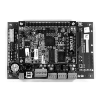
E-Link Gateway Installation Instructions10
Table 9: BAS Output Protocol Quick Start Selections
APP Group
Switch B
Output Protocol Quick Starts
Switch Settings 8421Port 1 Port 3 Port 4
0
1
1. When making edits to User Report 4 (Port Configuration), Group Application Switch B must be set to zero. This setting
ensures that the edits are stored. Otherwise, the edits are overwritten to the default values assigned to the particular Group
Switch B setting the next time E-Link is reset, or power is cycled. Edits made in any other User Reports do not require
alterations to either bank of Group Application switches. For standard set-up, not requiring modifications via User Report 4,
use application switch B, settings 1 to 14.
0000MS/TP, AUTO, N, 8, 1 Modbus, 19,200, N, 8, 1 Terminal
1
2, 5
2. The Terminal setting on Port 4 is restricted for factory use only.
To comply with the LONMARK® specification, all data transmitted on the LONWORKS network must be expressed in SI units
(metric units). The L
ONWORKS ProtoCessor performs no unit conversions; it assumes that the data supplied is already
correctly expressed.
0001MS/TP, AUTO, N, 8, 1 Modbus, 19,200, N, 8, 1 Terminal
2
2, 5
0010MS/TP, AUTO, N, 8, 1 Modbus, 19,200, N, 8, 2 Terminal
3
2, 5
0011MS/TP, AUTO, N, 8, 1 N2, 9,600, N, 8, 1 Terminal
4
2, 5
0100N2, 9,600, N, 8, 1 MS/TP, 38,400, N, 8, 1 Terminal
5
2, 5
0101Modbus, 19,200, N, 8, 1 MS/TP, 38,400, N, 8, 1 Terminal
6
2, 5
0110Modbus, 19,200, N, 8, 2 MS/TP, 38,400, N, 8, 1 Terminal
7
2, 5
0111Modbus, 9,600, E, 8, 1 MS/TP, 38,400, N, 8, 1 Terminal
8
2, 5
1000Modbus, 9,600, N, 8, 1 MS/TP, 38,400, N, 8, 1 Terminal
9
3, 5, 6
3. Use Quick Start 9 and 11 if the equipment is supplying the data in SI units (the E-Link is not required to perform any
conversions, so it operates in pass-through mode).
1001N2, 9,600, N, 8, 1 Modbus, 19,200, N, 8, 1 L
ONWORKS – Pass through
10
4, 5,
6
4. Use Quick Start 10 and 12 if the equipment is supplying the data in Imperial units and the E-Link is required to convert these
units into SI.
5. Setting Switch T = ON, on the MAC address, forces TERMINAL mode of Port 3, at 57,600 baud, N, 8, 1. This setting is only
required to debug the E-Link Gateway’s operation, or access the User Reports.
6. Select Quick Starts 9 and 10 when connecting the E-Link Gateway to an ECO2 unit.
1010N2, 9,600, N, 8, 1 Modbus, 19,200, N, 8, 1 L
ONWORKS – Conversion
11
3, 5
1011Modbus, 19,200, N, 8, 2 N2, 9,600, N, 8, 1 LONWORKS – Pass through
12
4, 5
1100Modbus, 19,200, N, 8, 2 N2, 9,600, N, 8, 1 LONWORKS – Conversion
13
2, 5
1101Modbus, 9,600, E, 8, 1 Modbus, 19,200, N, 8, 2 Terminal
14
2, 5
1110MS/TP, 38,400, N, 8, 1 N2, 9,600, N, 8, 1 Terminal
15
7
7. Quick Starts 15 on APP Group B, and 63 on APP Group A, are reserved for field adjustments.
1111Reserved Reserved Terminal

 Loading...