E-Link Gateway Installation Instructions6
Wall Mounting
To mount the E-Link Gateway on a wall:
1. Check for proper clearances for the necessary
electrical and communications cable runs.
2. Ensure that power and communications wiring is in
compliance with all local, national, and regional
codes, and customer requirements.
3. Select a suitable location and mark the anchor
points. Ensure that the enclosure is level. See
Figure 5 for an example.
4. Drill the appropriate holes in accordance with the
type of wall anchor used.
5. Install the enclosure on the wall.
6. Check that the mounting is secure and the wiring
connections are correct and tight. Check that no
loose wire strands or other metal objects that could
cause a short circuit are on the circuit board.
7. Complete wiring as described in the Applying
Power section.
Applying Power
When using an enclosure type of E-Link Gateway,
power can be supplied from either a separate power
supply or the main terminal strip in the chiller panel.
Locate the power source within 0.9 m (3 ft) of the
E-Link Gateway, and protect it with a suitable fuse or
circuit breaker. Ensure the power is supplied from a
dedicated source and not controlled by a programmed
switch.
If the enclosure is mounted on a wall, the wiring from
the power source to the E-Link Gateway must always
run in a suitable conduit. To obtain the best
Electromagnetic Interference (EMI) and
Electromagnetic Compatibility (EMC) performance,
ensure that the conduit is bonded to the metal of both
enclosures. Scraping the paint around the knockouts
usually helps provide a better electrical connection
between the joining parts.
1. Connect a 1.29-1.02 mm (16-18 AWG) wire from a
reliable ground reference to the E-Link Gateway’s
incoming power ground lug. Do not remove the
existing wire that connects the ground lug to the
enclosure cover.
2. On 120 VAC applications, connect the Hot wire to
TB2 and the Neutral wire to TB1. Connect the
ground wire to a ground lug.
On 240 VAC applications, connect the Hot wire to
TB3 and the Neutral wire to TB1. Connect the
ground wire to a ground lug.
IMPORTANT: When wall mounting, make sure
there is no interference with other components in the
near vicinity. Use appropriate conduit to connect the
power and communications wiring.
IMPORTANT: Be careful not to damage the circuit
boards during installation.
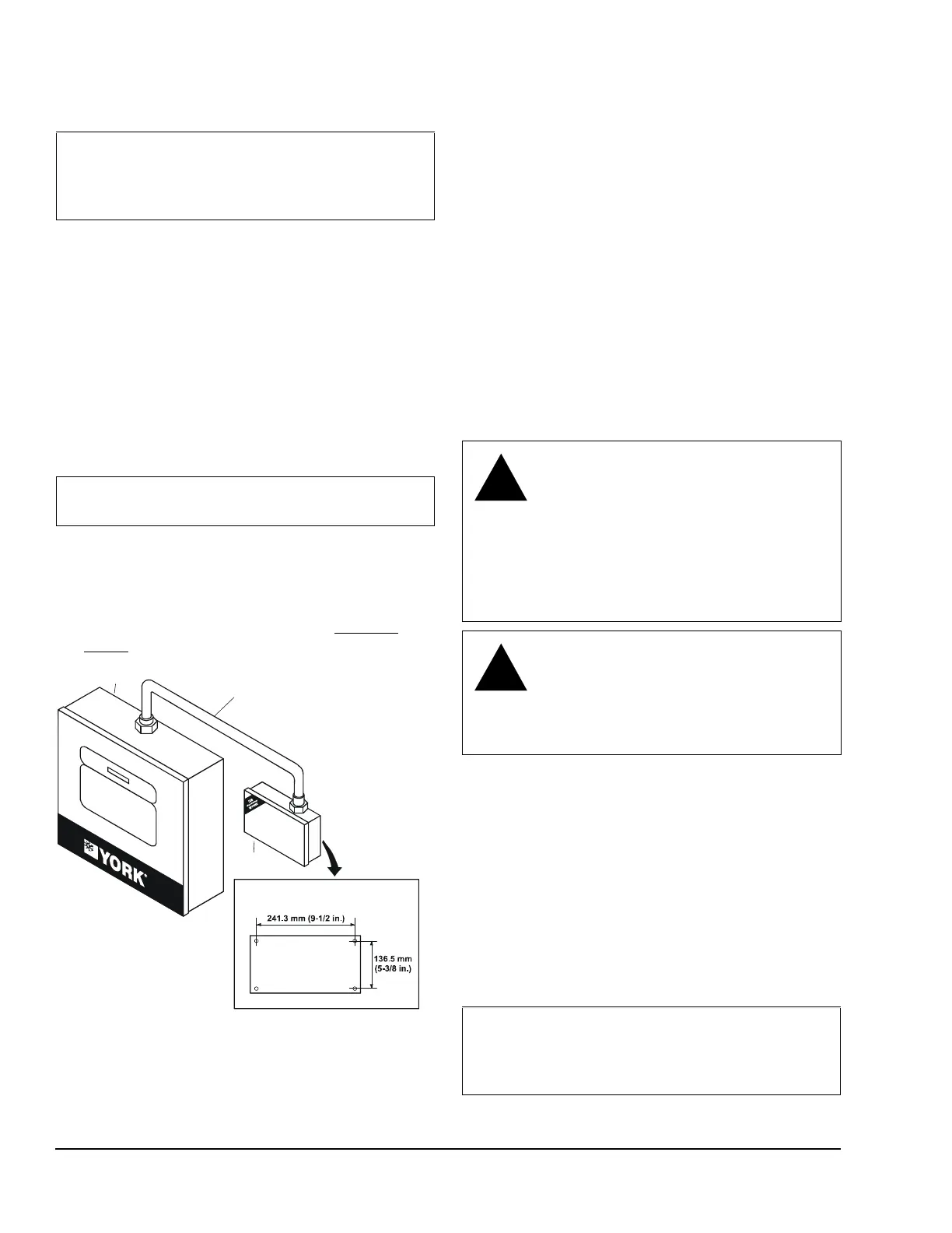
YORK Chiller
Micro Panel
Template for Mounting
on a Wall
Conduit
E-Link
Enclosure
FIG:WllMnt
WARNING: Risk of Electric Shock.
Disconnect or isolate all power supplies
before making electrical connections.
More than one disconnect or isolation
may be required to completely
de-energize equipment. Contact with
components carrying hazardous voltage
can cause electric shock and may result
in severe personal injury or death.
CAUTION: Risk of Property Damage.
Do not apply power to the system before
checking all wiring connections. Short
circuited or improperly connected wires
may result in permanent damage to the
equipment.
IMPORTANT: Use copper conductors only.
Make all wiring connections in accordance with
local, national, and regional regulations. Do not
exceed the E-Link Gateway’s electrical ratings.