E-Link Gateway Installation Instructions 5
Other Chiller Panel Installation
For all other applications, the E-Link Gateway includes
an optional enclosure. The optional enclosure does not
include communication cables due to the variety of
types and lengths that may be required.
The E-Link Gateway can be mounted as a stand-alone
enclosure either on the outside surface of the chiller
Micro Panel (close coupled), or on a smooth surface
within close proximity of the chiller panel enclosure.
For mounting on a Micro Panel, the line voltage power
is supplied by a power source in the Micro Panel.
Mounting on a Micro Panel
To mount the E-Link Gateway on a Micro Panel:
1. Disconnect power to the chiller Micro Panel.
2. Make sure the E-link Gateway enclosure fits
properly and that no obstructions, such as internal
boards, switches, or external conduit, prevent
mounting or servicing of the panel. See Figure 4 for
examples of good mounting locations.
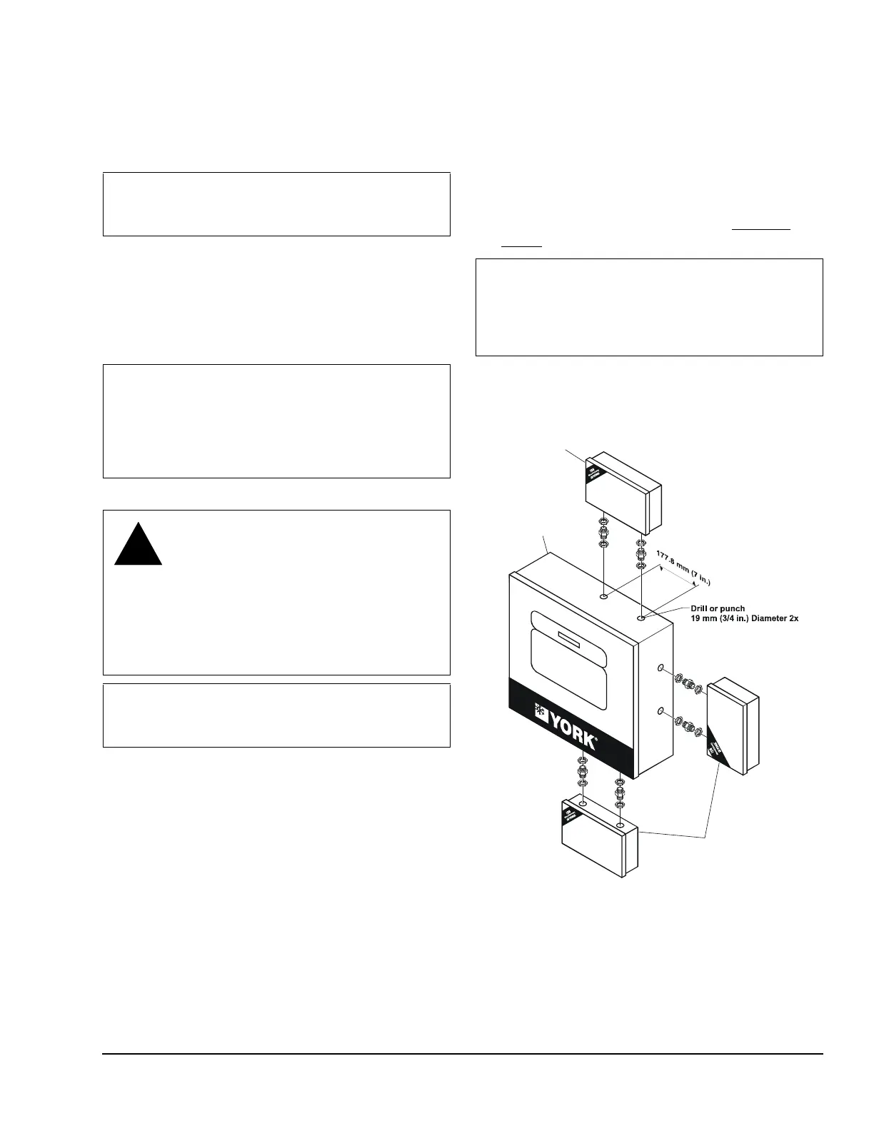
3. Locate and remove the two plastic caps in the
bottom of the E-Link Gateway enclosure.
4. Mark an appropriate place on the enclosure for a
matching set of knock out holes. Mark and drill, or
punch, two holes in the Micro Panel.
5. Using two bulkhead pipe couplers, attach the
E-Link Gateway enclosure to the Micro Panel.
6. Complete wiring as described in the Applying
Power section in this document.
Note: Use of bulkhead pipe couplers provides
sufficient clearance to allow removal of the E-Link
Gateway cover.
IMPORTANT: Never install the E-Link Gateway
outside the confines of a building unless within
another enclosure rated IP 65/NEMA 4x or higher.
IMPORTANT: Make sure that the cover is securely
fastened to the enclosure and the internal ground
wire is attached before placing the Gateway in
operation. These steps help to minimize Radio
Frequency Interference (RFI) from being generated
and picked up.
WARNING: Risk of Electric Shock.
Disconnect or isolate all power supplies
before making electrical connections.
More than one disconnect or isolation
may be required to completely
de-energize equipment. Contact with
components carrying hazardous voltage
can cause electric shock and may result
in severe personal injury or death.
IMPORTANT: When attaching the E-Link Gateway
to a Micro Panel, ensure the E-Link Gateway does
not impede access to other components.
IMPORTANT: Be careful not to damage the E-link
Gateway or Micro Panel’s circuit boards during the
installation. Protect all circuit boards from metal
chips, which may cause short circuits if left on the
boards at startup.
E-LINK
Enclosure
YORK Chiller
Micro Panel
Mounting
Locations
FIG:MntEqu ip
Figure 4: Mounting on the Equipment