E-Link Gateway Installation Instructions4
IPU-II Panel Installation
(Installation Kit Not Available in Europe)
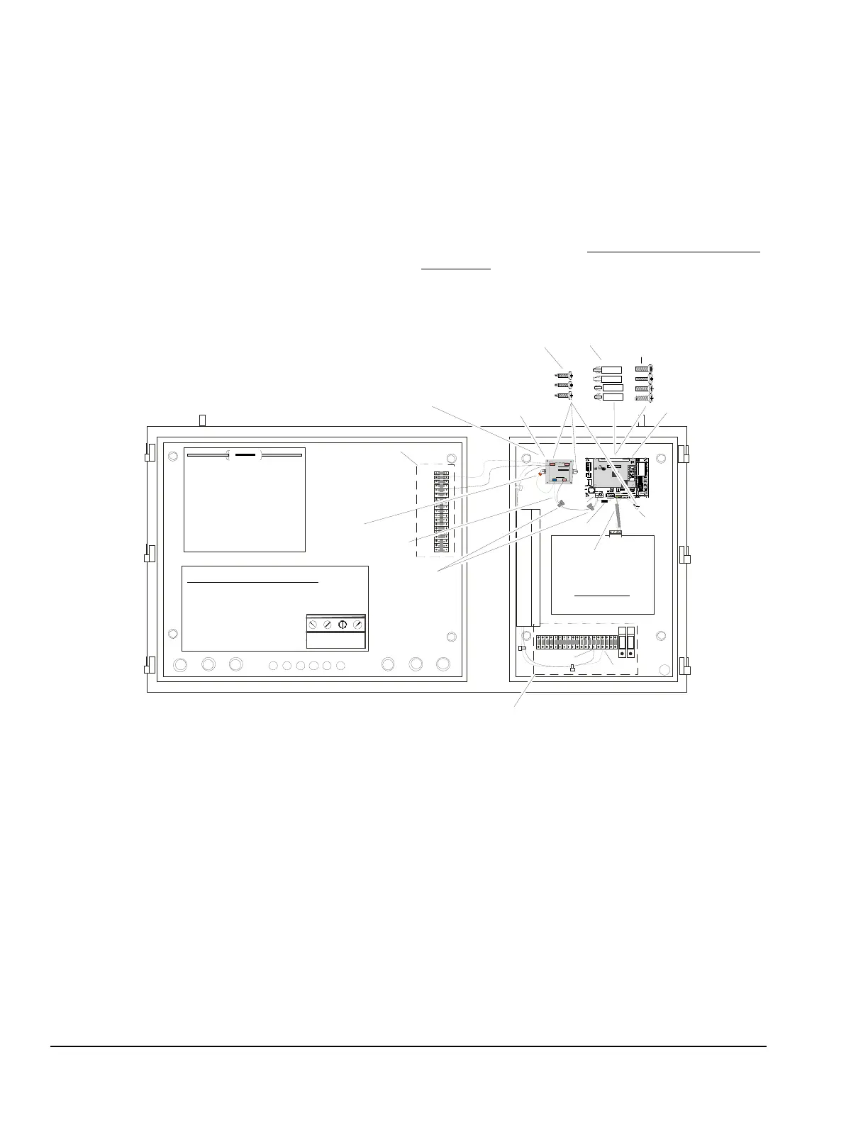
1. Attach the E-Link Gateway board to the panel in
the upper right side of the enclosure using the four
expansion screws and nuts provided in the IPU-II
Panel Installation Kit (see Figure 3).
2. Attach the 24 VAC transformer to the panel to the
left of the E-Link board using two screws (see
Figure 3).
3. Connect the communications cable (included with
the kit) between the E-Link board and IPU-II Micro
board.
4. Connect the transformer to the terminal block.
5. Connect the transformer to E-Link. Secure the
wiring with tie-wraps.
6. Connect the resistor if the RS-485 2-wire operation
is required.
7. Connect the communications cable shielded
ground to the ground screw.
The E-Link Gateway is now ready to be configured
using Quick Start; see the Commissioning a Standard
Application section in this document.
Expansion
Nut
Expansion
Nut
Screw
Sheet
Metal
Screw
Resisto
Wiring
Harness
Tie
Wrap
T
B5
TB 2
E-LIN
Ground
Communication
Wiring Harness
Com
Ground
T B 1
T B 5
The Resistor is used for BAS
RS485 2 Wire Connection.
Connect one end of the
Resistor to the COM o
TB5 (24 VAC) and the othe
to Port 1 COM.
Use this resistor only if the
BAS wiring utilizes a 2 Wire
communication trunk
Communication Wiring Harness:
Connect to Micro Board
TB1 as Follows:
Wire Color / Terminal
Red / +
Black / -
+
-
REFSHLD
TB 1 RS485
F
I
G
:
I
P
U
p
n
l
i
n
s
t
Terminal block location
for YCAL-D, YCAL-E, and YLAA.
Terminal block location
for YCAL-C, YCWL, and
Primary Powe
Figure 3: IPU-II Panel Installation (Installation Kit Not Available in Europe)