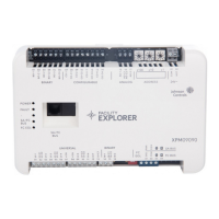
Figure 11: UI Current loop jumper positions
Setting the current loop jumper to the Enabled position,
connects an internal 100 ohm resistor across the UI
terminals, which maintains the 4-20 mA current loop
circuit even when power to the expansion module is
interrupted or off.
Important: Current Loop jumpers must be in the
Disabled (default) position for all UIs that are not set
up to operate as 4-20 mA analog inputs.
Important: A current loop jumper must be in the
Enabled position to maintain a closed 4-20 mA
current loop.
The following tables identify the current loop switches
associated with each UI on the XPM09090 and XPM04060
models.
Table 7: XPM09090 UI Inputs and jumper labels
Universal Input
label
Jumper label on circuit board
UI-1 J13
UI-2 J14
UI-3 J15
UI-4 J16
UI-5 J17
Table 7: XPM09090 UI Inputs and jumper labels
Universal Input
label
Jumper label on circuit board
UI-6 J18
UI-7 J19
Table 8: XPM04060 UI Inputs and jumper labels
Universal Input
label
Jumper label on circuit board
UI-1 J10
UI-2 J11
UI-3 J12
Setting up a local display
XPM models do not have an integral display, but can be
connected to an FX-DIS1710 Local Controller Display. For
detailed information about setting up and operating a
remotely connected FX-DIS1710 display, refer to the FX-
DIS Local Controller Display Technical Bulletin (LIT-12011666).
Commissioning
You commission expansion modules with the Controller
Configuration Tool (CCT) software using either Mobile
Access Portal (MAP) Gateway, a ZFR wireless dongle, or
in passthrough mode when connected to FX-SNC. Refer
to the Controller Tool Help (LIT-12011147) for detailed
information on commissioning expansion modules.
Troubleshooting expansion modules
Observe the Status LEDs on the front of the expansion module. Table 9 provides LED status indicator information for
troubleshooting the expansion module. To troubleshoot an integral or local controller display, refer to the FX-DIS1710
Local Controller Display Technical Bulletin (LIT-12011666).
LED status and states
Table 9: Status LEDs and description of LED states
LED label LED color Normal LED state Description of LED states
POWER Green On Steady
Off Steady = No Supply Power or the controller’s polyswitch/resettable fuse is
open. Check Output wiring for short circuits and cycle power to controller.
On Steady = Power Connected
FAULT Red Off Steady
Off Steady = No Faults
On Steady = Device Fault; no application loaded
Blink - 2 Hz = Startup in progress, not ready for normal operation
Rapid blink = SA Bus communications issue
SA/FC BUS Green Blink - 2 Hz
Blink - 2 Hz = Data Transmission (normal communication)
Off Steady = No Data Transmission
On Steady = Communication lost, waiting to join communication ring
EOL Amber
Off (Except on
terminating
devices)
On Steady = EOL switch in ON position
Off Steady = EOL switch in Off position
F4-XPM Expansion Modules Installation Guide 17
 Loading...


